The Ultimate Guide to Metal Oxide Varistors (MOVs)
2024-05-31
25398
Catalog

Figure 1: Metal Oxide Varistors
Introduction to Metal Oxide Varistors (MOV)
A Metal Oxide Varistor (MOV) is a major component used in electronic circuits. It is often identified by its small, circular blue or orange disk on the AC input side of power supplies. The MOV acts as a variable resistor, adjusting its resistance according to the applied voltage. Under normal conditions, it has high resistance, but when high voltage is applied, its resistance drops sharply, functioning like a short circuit. This special feature makes MOVs important for protecting electronic circuits from sudden voltage increases.

Figure 2: Metal Oxide Varistors
MOVs are usually installed in parallel with a fuse. This setup allows them to absorb and dissipate excess voltage, protecting sensitive components from damage. Unlike other variable resistors like potentiometers, an MOV can change its resistance based on voltage variations. In normal operation, an MOV has high resistance and draws minimal current. However, during voltage surges, its resistance decreases substantially, allowing it to conduct high current and clamp the excess voltage.
This ability makes MOVs extremely effective in surge protection applications within electronic networks. MOVs quickly respond to voltage spikes, helping electronic devices last longer and work reliably.
How Metal Oxide Varistors (MOV) Works?
Metal Oxide Varistors (MOVs) is a voltage surge protection component. Usually have high resistance and draw very little current. When a voltage surge exceeds a specific level called the clamping voltage, the MOV's resistance drops sharply. This change lets the MOV conduct more current, dissipating excess energy and protecting connected equipment from damage.
MOVs are made to handle short, sudden voltage spikes, not long-term overvoltage. Repeated surges can wear them out, lowering their clamping voltage and eventually causing failure.

Figure 3: MOV as Voltage Surge Protection Device
In practical circuits, MOVs are typically used with fuses. Under normal conditions, the MOV's high resistance ensures that current flows through the main circuit, not the MOV. During a voltage spike, the MOV's resistance decreases dramatically, allowing it to divert the excess current. This often causes the fuse to blow, disconnecting the circuit from the harmful surge and protecting the main components.
While this process effectively protects the circuit, it puts stress on the MOV. Frequent voltage spikes can wear out the MOV faster, reducing its ability to protect the circuit. Therefore, MOVs are very effective for transient surge protection but need monitoring & occasional replacement to guarantee continued protection.
Composition and Structure of Metal Oxide Varistors (MOVs)
A Metal Oxide Varistor (MOV) is mainly made of ceramic powders of metal oxides, with zinc oxide being the main component. Small amounts of other oxides like cobalt, manganese, and bismuth are also included. These powders are pressed between two metal plates that act as electrodes. This setup forms many diode junctions between the grains of metal oxides, creating a large array of connected diodes.
Under normal conditions, when a low voltage is applied, only a tiny, harmless reverse leakage current flows through these junctions. However, when a high voltage is applied, the junctions break down due to electron tunneling and avalanche breakdown, allowing a significant current to flow. This enables the MOV to conduct electricity and protect the circuit by clamping the excess voltage.

Figure 4: Metal Oxide Varistors Structure
MOVs are designed to conduct only when the applied voltage exceeds a specific threshold. Once the voltage drops back below this threshold, the MOV stops conducting and returns to its high-resistance state.
MOVs come in various formats to fit different applications, including disk, axial leaded, block and screw terminal, and radial leaded configurations. They can be connected in parallel to handle higher energy loads or in series to achieve higher voltage ratings. This flexibility allows MOVs to be tailored to specific protection needs in diverse electronic systems.
Electrical Characteristics of MOVs Explained
Understanding the electrical characteristics of Metal Oxide Varistors (MOVs) is needed for their proper use in protecting electronic circuits. One key characteristic is their static resistance, which changes inversely with the applied voltage.

Figure 5: MOV Static Resistance Characteristic
Normally, MOVs have high resistance, allowing minimal current flow. However, as the voltage increases, their resistance decreases. This behavior can be shown through a resistance-voltage curve, demonstrating how MOVs adjust their resistance to protect the circuit.
Another important aspect is the voltage-current (V-I) characteristics of MOVs. It is nonlinear, unlike regular resistors. At low voltages, MOVs maintain high resistance with little current flow.

Figure 6: Voltage-Current (V-I) Characteristics of MOV
As the voltage approaches the clamping level, the resistance drops, allowing more current to flow. This change is symmetrical and works in both directions, similar to two Zener diodes connected back-to-back. This feature makes MOVs highly conductive at clamping voltages. It effectively protecting the circuit by diverting excess current away from sensitive components.
MOVs also have inherent capacitance due to their construction, where the device acts as a dielectric medium between two electrodes. This capacitance can impact circuit performance, especially in AC circuits, where it may cause leakage currents because of frequency-dependent reactance. While the capacitance effect is minimal in DC circuits, it can be more significant in AC circuits, requiring careful consideration in design & application to ensure optimal protection without unintended circuit interference.
Selecting the Right MOV for Your Application
Choosing the right Metal Oxide Varistor (MOV) for your application requires understanding several key parameters:
Maximum Working Voltage
The maximum working voltage is the steady-state DC voltage that the MOV can handle without causing excessive leakage current. Ensure that your system's operating voltage does not exceed this value to avoid premature degradation of the MOV.
Clamping Voltage
The clamping voltage is the point at which the MOV starts to conduct and protect the circuit. When the voltage surpasses this threshold, the MOV dissipates the excess energy, clamping the voltage to a safe level. Select an MOV with a clamping voltage suitable for the protection level you need.
Surge Current
The surge current parameter indicates the peak current the MOV can withstand without damage, typically specified for a particular duration, such as 8/20 microseconds. Make sure the MOV can handle the highest surge current your application might encounter.
Surge Shift
Surge shift refers to the reduction in clamping voltage after the MOV has been exposed to repeated surges. Over time, the clamping voltage can decrease, affecting the MOV's performance. Consider this factor if your application is prone to frequent surges.
Energy Absorption
Energy absorption is the maximum energy the MOV can dissipate during a surge. It usually expressed in joules for a specific waveform, such as 10/1000 microseconds. Choose an MOV that can absorb the expected surge energy without failing.
Response Time
Response time is the duration it takes for the MOV to start conducting after a surge, typically around 100 nanoseconds. A fast response time is needed for effective protection against sudden voltage spikes.
Maximum AC Voltage
The maximum AC voltage is the highest RMS voltage the MOV can handle continuously. Match this with the operating voltage of your AC system to ensure definitive protection.
Leakage Current
Leakage current is the small current the MOV draws when operating below the clamping voltage. It indicates the behavior of the MOV under normal conditions. Low leakage current is desirable to minimize energy loss and heat generation during regular operation.
Common Applications of MOVs in Everyday Devices

Figure 7: Metal Oxide Varistors
Metal Oxide Varistors (MOVs) are incredibly versatile in various applications. Below highlights the MOVs broad range of uses, from everyday household devices to specialized industrial and communication systems.
Household and General Electronics: MOVs are used in both single-phase and line-to-line protection in AC and DC circuits. They safeguard household appliances, power supplies, and other electronic devices from voltage spikes caused by lightning strikes or power grid fluctuations. In surge protectors, MOVs absorb excess voltage, preventing it from reaching connected electronics such as computers, televisions, and other valuable devices.
Semiconductor Devices: In semiconductor devices, MOVs provide protection for transistors, MOSFETs, and thyristors. They clamp down on transient voltages that could otherwise damage these sensitive components. MOVs also protect motor-operated devices from contact arcing, which can occur when switches & relays open or close, potentially causing harmful voltage spikes.
Telecommunications: In the telecommunications sector, MOVs safeguard lines from lightning strikes and other transient events that can disrupt service. This protection guarantee reliable operation of communication networks, preventing service interruptions caused by voltage spikes.
Industrial Applications: Industrial applications of MOVs include high-energy AC line protection, where they help prevent equipment failure due to sudden voltage surges.
Data Systems: MOVs are used in data systems to protect sensitive data processing and storage equipment. By clamping down on voltage surges, they make sure the integrity of data systems.
Microwave Technology: In microwave technology, MOVs have niche applications such as in microwave mixers for modulation, detection, and frequency conversion processes.
Step-by-Step Guide to Designing an MOV Protection Circuit
Designing a Metal Oxide Varistor (MOV) protection circuit is important for protecting electronic devices from voltage spikes and surges. Here’s a detailed, step-by-step guide to help you design an effective MOV protection circuit:
• Determine Continuous Working Voltage
Identify the regular operating voltage of your circuit. Choose an MOV with a maximum AC or DC voltage rating slightly higher than this value. This prevents the MOV from activating during normal operation.
• Assess Energy Absorption Capability
Evaluate the maximum surge energy your circuit might experience. Select an MOV that can absorb more energy than the maximum expected surge. This ensures the MOV can handle large surges without getting damaged.
• Check Peak Transient Current
Determine the peak transient current that the MOV needs to withstand. Ensure the MOV’s surge current rating meets or exceeds this value so it can survive the initial impact of a surge.
• Calculate Power Dissipation
Consider the power dissipation capacity of the MOV. Make sure it can handle the expected power during surges. Understand how much energy the MOV will convert into heat and ensure it can manage this heat without degrading.
• Select Appropriate Clamping Voltage
Choose an MOV with a suitable clamping voltage for your circuit. The clamping voltage is the maximum voltage the MOV will allow during a surge. It should be below the maximum voltage your circuit can tolerate but high enough to avoid clamping during normal voltage fluctuations.
• Determine the Number of MOVs Needed
Depending on your circuit’s complexity and protection requirements, you might need more than one MOV. For enhanced protection, especially in high-energy environments, consider using multiple MOVs in parallel to share the load.
• Design the Circuit Layout
Plan your circuit layout carefully. Place the MOV as close to the power entry point of your circuit as possible to clamp surges before they spread. Make sure good electrical connections and minimize lead lengths to reduce inductance, which can affect the MOV’s performance.
• Add Fuses for Additional Protection
Incorporate fuses or circuit breakers in series with the MOV. These components will disconnect the MOV from the circuit if it fails or overheats, preventing further damage. Choose fuses with ratings that match the MOV’s specifications.
• Implement Thermal Protection
Consider adding thermal protection, such as thermal cutoffs or resettable thermal switches. These devices protect the MOV from overheating by disconnecting the circuit when excessive temperatures are detected.
• Test the Circuit
Before finalizing your design, test the circuit under controlled conditions. Simulate surge events to ensure the MOV responds correctly and protects the circuit. Check for any signs of overheating or degradation in the MOV during these tests.
• Monitor and Maintain
Once the MOV protection circuit is implemented, regularly monitor its performance. Inspect the MOV for any signs of wear or damage and replace it if necessary. Keeping track of significant surge events can help predict when the MOV might need replacement.
MOVs vs. Other Surge Protection Devices Comparison
Here's a comparison table for Metal Oxide Varistors (MOVs), Transient
Voltage Suppression (TVS) Diodes, and Gas Discharge Tubes (GDTs).

Figure 8: MOV, TVS, GDTs
|
Feature |
Metal Oxide Varistors (MOVs) |
Transient Voltage Suppression (TVS) Diodes |
Gas Discharge Tubes (GDTs) |
|
Response Time |
Fast, but slower than TVS diodes |
Very fast, almost instantaneous |
Slower compared to MOVs and TVS diodes |
|
Energy Absorption |
High energy absorption capacity |
Lower energy absorption capacity |
High energy absorption capacity |
|
Clamping Voltage |
Clamps voltage to a safe level |
Precise clamping voltage |
Requires higher voltage to activate |
|
Degradation |
Degrades over time with repeated surges |
Minimal degradation over time |
Long lifespan, minimal degradation |
|
Cost |
Cost-effective |
Generally, more expensive |
Moderate cost |
|
Applications |
Wide range: household electronics, industrial systems |
Protecting sensitive electronic components |
Telecommunications, power distribution systems |
|
Effectiveness |
Effective, but performance diminishes with multiple surges |
Highly efficient at clamping transient voltages |
Effective for handling large surges |
|
Ideal For |
General surge protection needs |
Protecting very sensitive electronics |
High-energy surge environments where speed is less critical |
Chart 1: MOVs vs. Other Surge Protection Components
Tips for Ensuring Long-Term Reliability of MOVs
Here are practical tips to help extend the lifespan and effectiveness of MOVs:
Choose the Right MOV for Your Application
Select an MOV that matches the voltage and current requirements of your application. Ensure the clamping voltage, energy absorption capacity, and peak current rating align with your system’s needs. Using an MOV with appropriate ratings helps it handle typical surges without degrading quickly.
Proper Installation
Install MOVs according to the manufacturer's guidelines. Make sure solid electrical connections and avoid excessive mechanical stress, which can damage the MOV and reduce its effectiveness. Correct installation helps maintain the MOV’s longevity.
Avoid Overloading
Avoid exposing MOVs to surges beyond their rated capacity. Overloading can cause permanent damage and shorten the MOV’s lifespan. Design your power system to handle potential surges without exceeding the MOV’s limits.
Use Thermal Protection
Incorporate thermal protection devices, such as thermal fuses or circuit breakers, into your surge protection system. These devices prevent overheating and potential failure of the MOV by disconnecting it during extreme conditions. Thermal protection guarantee MOV does not operate beyond its thermal limits.
Regular Inspection and Maintenance
Periodically inspect MOVs for signs of wear or damage. Look for discoloration, cracks, or changes in appearance, which can indicate deterioration. Replace any MOVs showing signs of wear to maintain effective surge protection. Regular maintenance helps catch potential issues before they lead to failure.
Environmental Considerations
Protect MOVs from harsh environmental conditions. Excessive heat, moisture, and corrosive environments can accelerate aging and reduce reliability. Place MOVs in a controlled environment whenever possible to maximize their lifespan. Use enclosures or protective coatings if necessary to shield MOVs from adverse conditions.
Monitor Surge Events
Keep track of significant surge events that the MOVs have encountered. Frequent or high-magnitude surges can degrade MOVs over time. Monitoring helps decide when it might be time to replace them. Implementing a monitoring system can provide valuable data on the performance and stress levels experienced by the MOVs.
Quality and Standards
Use high-quality MOVs from reputable manufacturers. Ensure they meet industry standards and certifications, indicating they have been tested for reliability and performance. High-quality MOVs are more likely to provide consistent protection and have a longer operational life.
Design Redundancy
In critical applications, consider designing redundancy into your surge protection system. Using multiple MOVs in parallel can share the load and provide backup if one MOV fails. Redundancy enhances the reliability of your protection system, especially in environments with frequent or severe surges.
Troubleshooting and Replacing Damaged MOVs

Figure 9: Troubleshooting Damaged MOVs
Metal Oxide Varistors (MOVs) can wear out or get damaged over time.
Here are some steps to troubleshoot and replace damaged MOVs:
Recognize the Signs of Damage
Inspect the MOVs for visible signs of damage. Look for discoloration, burn marks, cracks, or a swollen appearance. These signs suggest the MOV has absorbed a significant surge and may be compromised. Regular visual checks can help catch issues early.
Use a Multimeter to Test the MOV
To determine if an MOV is still functioning, use a multimeter. First, disconnect the power supply to the device. Set the multimeter to measure resistance and connect the probes to the MOV terminals. A healthy MOV should show very high resistance. If the multimeter shows low or zero resistance, the MOV is damaged and needs replacement.
Safety Precautions
Before replacing a damaged MOV, ensure the power is completely turned off and the device is unplugged. This prevents any risk of electrical shock while you work on the device. Always prioritize safety to avoid accidents.
Remove the Damaged MOV
Carefully desolder the damaged MOV from the circuit board using a soldering iron. Heat the solder joints and remove the MOV gently to avoid damaging the circuit board or other components. Proper technique helps preserve the integrity of the board.
Select a Replacement MOV
Choose a replacement MOV that matches the voltage and current ratings of the original. This ensures the new MOV will provide adequate protection without overloading the circuit. Matching the specifications is required for effective protection.
Install the New MOV
Place the new MOV in the same position as the old one and solder it to the circuit board. That will ensure a good electrical connection. Double-check your work to make sure there are no loose connections or solder bridges. Proper installation guarantee dependable performance.
Test the Replacement
After installing the new MOV, reconnect the power supply and turn on the device. Check if it operates normally. Use a multimeter to verify the new MOV’s resistance, if it shows high resistance, it’s not shorted. This step confirms the MOV is correctly installed and functional.
Monitor Performance
Keep an eye on the device’s performance over time. If the device continues to encounter frequent surges, it may indicate a need for additional surge protection measures or higher-rated MOVs. Regular monitoring helps maintain long-term protection and can prevent future failures.
Conclusion
Understanding Metal Oxide Varistors (MOVs) is important for keeping your electronic devices safe from voltage spikes. In this guide, we’ve explained what MOVs are, how they work, and where they are used. We’ve also covered how to choose the right MOV, design a protection circuit, and keep your MOVs working well over time. By following these tips, you can protect your electronics and make sure they last longer. Remember, proper use & regular checks of MOVs are key to good surge protection. Keep your devices safe and enjoy knowing they are well-protected.
Frequently Asked Questions [FAQ]
1. How do you calculate the specifications for an MOV?
To calculate the specifications for a Metal Oxide Varistor (MOV), you need to look at a few key factors: maximum continuous operating voltage (MCOV), clamping voltage, energy rating, and peak current rating. The MCOV should be higher than the system's normal operating voltage. The clamping voltage should be low enough to protect your devices but high enough to avoid unnecessary clamping. The energy rating should be enough to handle the surges you expect, and the peak current rating should exceed the highest surge current you anticipate. These factors ensure the MOV can protect your system properly.
2. What causes a metal oxide varistor to fail?
A metal oxide varistor can fail due to several reasons: too much surge current, frequent surges, prolonged overvoltage, or aging. Too much surge current can cause physical damage, while frequent surges can wear out the varistor material over time. Long exposure to high voltage stresses the MOV beyond its limits, leading to failure. Environmental factors like high temperatures & humidity can also speed up aging and degradation.
3. How can you tell if a varistor is still working?
To check if a varistor is working, inspect it for burn marks, cracks, or discoloration. Use a multimeter to measure its resistance. A good varistor has very high resistance when no voltage is applied. If it shows low resistance or seems shorted (near zero ohms), it is likely damaged & needs to be replaced. You can also test its clamping voltage with a known voltage to see if it is functioning correctly.
4. How long does a metal oxide varistor last?
The lifespan of a metal oxide varistor depends on its use and environment. Under normal conditions with few surges, an MOV can last several years to over a decade. In places with frequent or severe surges, its life may be shorter. Regular checks and tests help ensure the MOV is still working and indicate when it might need replacing.
5. Do varistors have a specific direction for installation?
No, varistors do not have a specific direction for installation. They are non-polarized, meaning you can connect them either way in the circuit. They protect against voltage surges in both directions. Just follow the manufacturer’s guidelines for placement & mounting to make sure they work correctly.
function test. The highest cost-effective products and the best service is our eternal commitment.
Hot Article
- LM358 Dual Operational Amplifier Comprehensive Guide: Pinouts, Circuit Diagrams, Equivalents, Useful Examples
- Are CR2032 and CR2016 Interchangeable?
- Understanding the Differences ESP32 and ESP32-S3 Technical and Performance Analysis
- Choosing the Right Battery: A Guide to AG4, LR626, LR66, 177/376/377, SR626, and SR626SW Equivalents
- BC547 Transistor Basics: Pinout, Application Circuits, Alternative/Complementary Models
- NPN vs. PNP: What's the Difference?
- esp32 vs stm32: which microcontroller is better for you?
- What Is a MOSFET and How It Works?
- Electrical Relay Basic: Working Operation, Types and Uses
- PNP Transistors: Structure, Working Principle and Application
 Everything You Need to Know About Transient Voltage Suppressor Diode
2024-06-03
 What is a TRIAC?
2025-09-16
Hot Part Number
 C0603C0G1E9R1C
 C1005CH1H271J050BA
 GRM188R71E392KA01D
 CGJ2B2X7R1H472K050BA
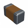 06031U390GAT2A
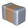 C2012X7R1E155M125AC
 12065C102JAT2A
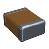 12102U131JAT2A
 GQM1555C2D200FB01D
 C3216JB1A156M160AC
- MCP6549-E/ST
- SST39VF3201-70-4I-EKE
- BD7905BFS-E2
- MAX6971AUG+T
- ICL3221EIVZ-T
- VI-2T3-EY
- SST12CP11-QVCE
- RT0402BRE0747R5L
- 2MBI600N-060
- BSM150GB120DN1
- V375A5C400AN
- FDMS86163P
- LTC4366HTS8-2#TRMPBF
- ADS8339IDGSR
- BLUENRG-MSCSP
- TMS320F28375SPZPT
- FS32K144HRT0MLLT
- T491D106M035AT7450
- TPS61200DRCT
- T491X687K006ZTZV13
- LTC2305HMS#TRPBF
- LF444CM
- ADSP2186KST-133
- BDP953E6327
- HS75438DTR
- LFX125B-03F256C
- LMC6035ITLX
- NH82801IO
- SM5852CS
- SP3249ECA-1
- TC74LCX126FT
- GT24C02-2SLI-TR
- STC10F08XE35I-LQFP44
- ALC5684-CG
- M30262F8GP#U3
- SPHE1510A-8BR-HI08N
- ICSU2A877AHLF
- MAX1181ECM+
- BTS5200-1ENA