P-Channel MOSFET: Symbol, Modes, and Applications
2025-05-07
50415
Catalog
Overview of P-Channel MOSFET
A P-Channel MOSFET is a type of transistor used to control the flow of electricity in a circuit. It's part of the MOSFET (Metal-Oxide-Semiconductor Field-Effect Transistor) family, which is widely used for switching and amplifying electronic signals. It controls the flow of electricity. A P-Channel MOSFET turns on (lets current flow) when the voltage at its gate is lower than the voltage at its source. It turns off (stops the flow) when the gate voltage is equal to or higher than the source voltage.
How Does P-Channel MOSFET Work?

Figure 1: P-Channel MOSFET Work Diagram
A P-Channel MOSFET is a smart switch that controls how electricity flows in a circuit. It has three parts: the Gate, Source, and Drain. When the Gate is at the same or higher voltage than the Source, the switch stays off and electricity can’t pass through. But when the Gate voltage drops and becomes lower than the Source (more negative), the switch turns on and electricity flows from the Source to the Drain. It's like a door that only opens when you gently pull it in the right direction. P-Channel MOSFETs are often used to control power on the top side of a circuit, like turning a device on or off.
Operating Modes of P-Channel MOSFETs
Enhancement Mode P-Channel MOSFET
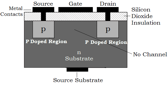
Figure 2: Enhancement Mode P-Channel MOSFET
This type is normally off when no voltage is applied to the gate. It only turns on when the gate voltage is more negative than the source. It's often used in switching applications where you want the circuit off by default.
Depletion Mode P-Channel MOSFET

Figure 3: Depletion Mode P-Channel MOSFET
This type is normally on even without any gate voltage. To turn it off, you need to apply a positive voltage to the gate. It's useful when current should flow unless you decide to stop it.
Different Types of P-Channels MOSFET
Surface-Mount P-Channel MOSFET
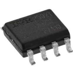
Figure 4: Surface-Mount P-Channel MOSFET
These are small and compact, made for surface-mounting directly on PCBs. Common in phones, laptops, and other space-saving electronics.
Through-Hole P-Channel MOSFET
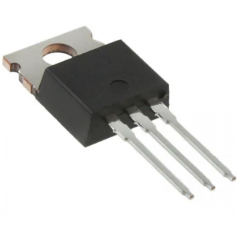
Figure 5: Through-Hole P-Channel MOSFET
These have longer legs and go through holes in the board. They're easier to handle, especially in DIY and prototyping projects.
Power P-Channel MOSFET
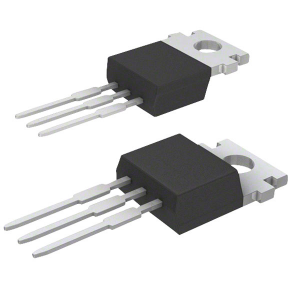
Figure 6: Power P-Channel MOSFET
Built to manage high voltages and currents. They're used in motor drivers, power converters, and high-side switching for heavy loads.
Structure of P-Channel MOSFET
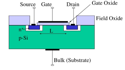
Figure 7: Structure of P-Channel MOSFET
This picture shows how a P-channel MOSFET is built inside a chip. The green part in the middle is called p-type silicon, it's like the base or body of the switch. On both sides, you see two blue blocks labeled n+, which are the source and drain—they help the electricity flow in and out.
In the middle, there's a space between the source and the drain. This space is called the channel, and it's controlled by something called the gate (the black bar on top). The gate doesn't touch the silicon directly, it's separated by a super thin glass-like layer called gate oxide, which acts like insulation.
When you put a negative voltage on the gate, it makes a path for the electricity to flow from the source to the drain. The field oxide on the sides helps keep everything separated and organized, kind of like fences on each side. The bottom part labeled bulk or substrate is where the whole structure sits.
Benefits of Using P-channel MOSFET
Simple High-Side Switching
P-Channel MOSFETs are great for switching the positive side (high side) of a power supply, which is often easier in certain circuit designs.
Easier Gate Drive for High-Side Control
They turn on when the gate is pulled lower than the source, so in many cases, you don't need extra gate driver circuits for switching.
Best for Low Current Control
They work well in low to medium current applications, such as powering small loads or sensors.
Complements N-Channel Designs
Used alongside N-Channel MOSFETs, they make full H-bridge circuits for motor control and power switching easier.
Reverse Polarity Protection
P-Channel MOSFETs can be used to protect circuits from reverse voltage connections, especially in battery-powered devices.
Lower EMI in Some Cases
Because of their switching position (on the high side), they can sometimes help reduce electromagnetic interference.
Uses of P-channel MOSFET
Power Management in Battery Circuits
They are often used to control the power flow in battery-powered devices, like laptops and mobile phones.
High-Side Switch in DC Circuits
P-Channel MOSFETs are used for switching the positive side of the power supply in DC circuits, making them ideal for high-side control.
Reverse Polarity Protection
They protect electronic devices by blocking current if the battery or power is connected the wrong way.
Motor Control
In H-bridge motor driver circuits, P-Channel MOSFETs are used with N-Channel ones to control the motor's direction.
LED and Light Strip Switching
They help in turning LEDs or light strips on and off from the high side, especially in automotive and lighting systems.
Load Disconnect Switches
Used as disconnect switches to fully cut off the load from the power supply when the system is off or in sleep mode.
How to Test P-Channel MOSFET?
You can check if a P-Channel MOSFET is working using a digital multimeter (DMM). This tool helps measure things like voltage, resistance, and diode behavior. In this test, we'll use the diode mode to see how the MOSFET responds to different conditions.
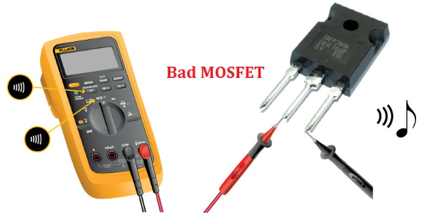
Figure 8: Digital Multimeter
• Step 1: Set Your Multimeter
Start by turning the multimeter to diode mode. This mode is usually shown by a triangle with a line next to it. It allows you to check if the internal parts of the MOSFET are functioning like a diode, which is useful for basic testing.
• Step 2: Identify the Pins
Next, find out which pin is the Source, Gate, and Drain. You can usually find this information on the component's datasheet or by searching the part number online. Knowing which pin is which is important so you can place your probes correctly.
• Step 3: Discharge the Gate
Before testing, it's important to remove any leftover electrical charge on the gate. To do this, touch all three pins together with a metal object or use your finger (only if safe to do so). This resets the MOSFET to its normal state.
• Step 4: Test the Body Diode
Now, place the black probe on the Source pin and the red probe on the Drain pin. You should see a reading between 0.4V and 0.7V—this means the internal diode is working. If you reverse the probes and the display shows "OL" (open loop), that's normal and confirms the diode is blocking current in the other direction.
• Step 5: Check Gate Control
To test if the gate is controlling the current, keep the black probe on the Source and touch the Gate pin with the red probe for a second to apply voltage. Now, place the red probe back on the Drain and check the reading. If the multimeter shows "OL", it means the MOSFET has turned on and is now blocking current, as expected.
Common Failures of P-Channel MOSFET
Gate Oxide Breakdown
This happens when the gate is exposed to too much voltage, which damages the thin insulating layer (oxide) under the gate. Once this layer breaks down, the MOSFET can no longer control current properly, and it may stay permanently on or off.
Overheating
If the MOSFET handles more current or power than it’s rated for, it can get too hot. Without proper heat sinks or cooling, this heat damages internal parts, leading to failure. Signs of this include burnt marks or cracks in the casing.
Electrical Overstress (EOS)
A sudden spike in voltage or current, like from a power surge, can stress the MOSFET’s internal components. This may cause short circuits between the source, drain, or gate, making the device stop working.
Avalanche Breakdown
If the voltage across the MOSFET goes beyond its maximum limit, it can cause an avalanche effect inside the semiconductor. This destroys the internal structure, and the MOSFET may short out or become completely open.
Gate-Source Leakage
A small but increasing current may start leaking between the gate and source over time. This usually happens due to aging or minor damage, and it prevents the MOSFET from fully turning off or on.
Mechanical Damage
Physical stress, like bending the leads too much or dropping the device, can crack or break the MOSFET. Even tiny cracks can lead to failure under heat or high voltage.
Conclusion
P-Channel MOSFETs are useful for saving power and protecting circuits. They're great for battery devices, motors, and lights. If you make, sell, or buy electronic parts, now is a good time to order P-Channel MOSFETs in bulk. Contact us today to get started.
function test. The highest cost-effective products and the best service is our eternal commitment.
Hot Article
- LM358 Dual Operational Amplifier Comprehensive Guide: Pinouts, Circuit Diagrams, Equivalents, Useful Examples
- Are CR2032 and CR2016 Interchangeable?
- Understanding the Differences ESP32 and ESP32-S3 Technical and Performance Analysis
- Choosing the Right Battery: A Guide to AG4, LR626, LR66, 177/376/377, SR626, and SR626SW Equivalents
- BC547 Transistor Basics: Pinout, Application Circuits, Alternative/Complementary Models
- NPN vs. PNP: What's the Difference?
- esp32 vs stm32: which microcontroller is better for you?
- What Is a MOSFET and How It Works?
- Electrical Relay Basic: Working Operation, Types and Uses
- PNP Transistors: Structure, Working Principle and Application
 TMAP Sensors - Definition and How They Work
2024-05-20
 From Theory to Practice: Utilizing Zener Diodes for Reliable Overvoltage Protection
2024-05-15
Frequently Asked Questions [FAQ]
1. Can I swap an N-Channel MOSFET with a P-Channel MOSFET?
Not directly. P-Channel and N-Channel MOSFETs turn on and off in opposite ways. A P-Channel turns on when its gate is lower than the source, while an N-Channel needs the gate to be higher. You’d need to adjust the circuit to match.
2. How much voltage do I need on the gate to turn on a P-channel MOSFET?
You need to make the gate voltage more negative than the source. Usually, it should be 2 to 10 volts lower than the source pin.
3. Why won't my P-Channel MOSFET turn off?
It might be because the gate voltage isn’t high enough compared to the source. Also, check for leftover charge on the gate or damage that’s causing a small current to leak between pins.
4. Should I put a resistor on the gate of a P-channel MOSFET?
Yes. A small resistor (10 to 100 ohms) helps slow down the switching just enough to prevent damage from sudden current changes. It also protects your control signal.
5. What does it mean to use a P-Channel MOSFET for high-side switching?
It means you're putting the MOSFET between the positive power supply and your load. P-Channel MOSFETs are great for this because they turn on when the gate is pulled lower than the power line.
Hot Part Number
 C0603C0G1E9R1C
 C1005CH1H271J050BA
 GRM188R71E392KA01D
 CGJ2B2X7R1H472K050BA
 06031U390GAT2A
 C2012X7R1E155M125AC
 12065C102JAT2A
 12102U131JAT2A
 GQM1555C2D200FB01D
 C3216JB1A156M160AC
- MCP6549-E/ST
- SST39VF3201-70-4I-EKE
- BD7905BFS-E2
- MAX6971AUG+T
- ICL3221EIVZ-T
- VI-2T3-EY
- SST12CP11-QVCE
- RT0402BRE0747R5L
- 2MBI600N-060
- BSM150GB120DN1
- V375A5C400AN
- FDMS86163P
- LTC4366HTS8-2#TRMPBF
- ADS8339IDGSR
- BLUENRG-MSCSP
- TMS320F28375SPZPT
- FS32K144HRT0MLLT
- T491D106M035AT7450
- TPS61200DRCT
- T491X687K006ZTZV13
- LTC2305HMS#TRPBF
- LF444CM
- ADSP2186KST-133
- BDP953E6327
- HS75438DTR
- LFX125B-03F256C
- LMC6035ITLX
- NH82801IO
- SM5852CS
- SP3249ECA-1
- TC74LCX126FT
- GT24C02-2SLI-TR
- STC10F08XE35I-LQFP44
- ALC5684-CG
- M30262F8GP#U3
- SPHE1510A-8BR-HI08N
- ICSU2A877AHLF
- MAX1181ECM+
- BTS5200-1ENA