NPN vs. PNP: What's the Difference?
2025-05-21
94628
Catalog

Figure 1. NPN and PNP Transistor Symbol
What is NPN Transistor?
An NPN transistor is a type of bipolar junction transistor (BJT) made from two N-type semiconductor layers separated by a thin P-type layer. NPN transistors, often called "sinking sensors" are widely used in electronic circuits for its speed, efficiency, & cost-effective manufacturing. NPN transistors are especially suited for high-speed switching & signal amplification because electrons—used as the primary charge carriers—move faster than holes used in PNP transistors. This higher mobility enables quicker response times, making NPN transistors ideal for dynamic applications such as digital computing, telecommunications, & signal processing.
What is PNP Transistor?
PNP transistors, referred to as "sourcing sensors". PNP transistor is a type of bipolar junction transistor (BJT) consisting of two P-type semiconductor layers separated by a thin N-type layer. It is often used in systems where a positive output signal indicates an active state, aligning with standard positive logic conventions. PNP transistors are used in industrial control environments, such as automation & safety systems. Their sourcing behavior—providing current to a load rather than sinking it—makes them suitable for applications requiring straightforward high-side switching & integration with positively referenced logic circuits.
How Do NPN and PNP Transistors Work?
Despite their structural differences, NPN and PNP transistors operate on the same principle: a small current at the base controls a larger current between the emitter & collector. What sets them apart is the direction of current flow & the type of charge carriers—electrons for NPN, holes for PNP.

Figure 2. NPN Transistor Working Principle
NPN Transistor Working Operation
The operation of an NPN transistor depends on controlling the current between the emitter & collector by adjusting the base current. When a small positive voltage is applied between the base & emitter (forward-biased base-emitter junction), electrons flow from the N-type emitter into the P-type base.
Since the base is narrow & lightly doped, only a small portion of electrons recombine with holes in the base. Most electrons pass through the base & are attracted to the collector, which is reverse-biased, allowing a large collector current to flow. This process forms the foundation of NPN transistor operation.
The collector current (IC) is directly controlled by the base current (IB). This ratio (IC/IB) defines the current gain (β) of the NPN transistor.
NPN transistor operates in three distinct regions depending on how the base-emitter & base-collector junctions are biased. Each region determines the transistor's behavior in a circuit.
In the active region, the base-emitter junction is forward-biased, while the base-collector junction is reverse-biased. Under these conditions, the transistor functions as a current amplifier. A small base current allows a much larger current to flow from the collector to the emitter. Most of the electrons injected by the emitter travel through the base & reach the collector.
In the cutoff region, both the base-emitter & base-collector junctions are reverse-biased. As a result, the transistor is effectively in the off state, & no current flows through the collector-emitter path. This region is commonly used when the transistor needs to act as an open switch.
In the saturation region, both the base-emitter & base-collector junctions are forward-biased. This condition turns the transistor fully on, allowing maximum current to flow from the collector to the emitter. In this region, the transistor behaves like a closed switch & is widely used in digital switching applications.
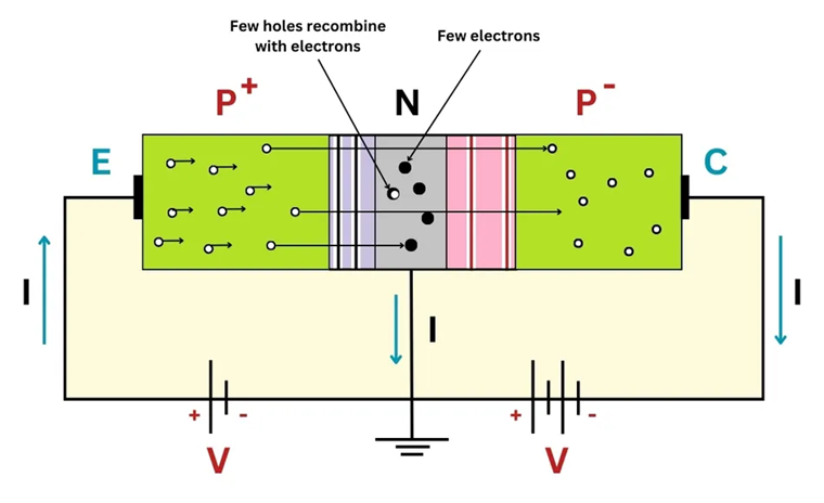
Figure 3. PNP Transistor Working Principle
PNP Transistor Working Operation
The working principle of PNP transistors is based on controlling the flow of current from the emitter to the collector by varying the small base current. Unlike NPN transistors, which use electrons as the majority carriers, PNP transistor operation depends on holes as the primary charge carriers. The PNP transistor working principle changes depending on how the junctions are biased. These conditions define the transistor’s three key operating regions: active, cutoff, & saturation.
In short, the difference in operation between NPN and PNP transistors lies in current direction & polarity. NPN transistors conduct when the base is more positive than the emitter, allowing current to flow from collector to emitter using electrons. PNP transistors conduct when the base is more negative than the emitter, allowing current to flow from emitter to collector using holes. Both work in active, cutoff, & saturation regions, but their opposite biasing & charge carriers define their roles in circuits.
Load Devices – PNP vs. NPN Output
Load devices can operate with both PNP & NPN outputs, offering flexibility when designing circuits & integrating components such as motors, relays, and solenoid valves.

Figure 4. PNP (sourcing) Configuration
In a PNP (sourcing) configuration, the sensor or control module provides a positive voltage to the load. The electrical load is connected between the output & the negative (common) side of the power supply. When the output turns on, current flows from the output to the load and then to ground. This setup is commonly used in systems where a high signal indicates activation and is compatible with solenoids equipped with diode protection to block back EMF.

Figure 5. NPN (sinking) Configuration
In an NPN (sinking) configuration, the sensor or control module provides a ground path. The load is connected between the positive supply & the output. When the output turns on, current flows from the power supply, through the load, and into the output (to ground). This setup is suitable for systems where a low signal indicates activation & also works well with protected solenoids. The ability to use either output type simplifies system design & supports flexibility in environments like industrial automation or multi-purpose equipment.
Applications of NPN and PNP Transistors
|
Application
Area |
NPN
Transistor Applications |
PNP
Transistor Applications |
|
Digital Logic Circuits |
Used as fast switches in microcontroller
outputs & logic gates |
Less common, used in circuits requiring
positive logic pull-up control |
|
Amplifier Circuits |
Common in class A/B amplifiers for
signal amplification |
Paired with NPN in push-pull amplifier
stages |
|
Motor Drivers |
Drives motors by sinking current through
the load |
Drives motors by sourcing current to the
load |
|
Relay Control |
Controls relay by grounding one side of
the coil |
Supplies power to the relay coil side |
|
PLC Systems (Industrial) |
Used with sourcing PLC input modules |
Preferred for sinking PLC input modules |
|
Sensor Outputs (e.g., Proximity) |
NPN sensors pull the signal low to
indicate activation |
PNP sensors push the signal high to
indicate activation |
|
LED Switching |
Controls LED by connecting cathode to
ground |
Controls LED by supplying current to the
anode |
|
Low-Side Switching |
Ideal choice (switch placed between load
& ground) |
Not suitable |
|
High-Side Switching |
Not ideal |
Ideal choice (switch placed between
power & load) |
|
Battery-Powered Devices |
Suitable for negative-ground systems |
Preferred for positive-ground systems |
Difference Between NPN vs. PNP Transistor
|
Feature |
NPN Transistor |
PNP Transistor |
|
Semiconductor Layer Structure |
Negative-Positive-Negative (N-P-N) |
Positive-Negative-Positive (P-N-P) |
|
Current Direction |
From collector to emitter |
From emitter to collector |
|
Base Activation |
Turns ON when a positive voltage/current
is applied to the base |
Turns ON when the base is at a lower
potential than the emitter (no current or slight negative) |
|
Deactivation Condition |
Turns OFF when base current is reduced
or removed |
Turns OFF when base becomes more
positive or current flows into base |
|
Voltage Requirement for Operation |
Requires a positive voltage at the base
relative to emitter |
Requires a negative voltage at the base
relative to emitter |
|
Internal Structure |
P-layer between two N-layers |
N-layer between two P-layers |
|
Switching Logic |
Sinking sensor – load is between
positive supply and collector |
Sourcing sensor – load is between
emitter and negative supply |
|
Operation |
Widely used in digital logic circuits
and switching |
Used in circuits where default ON state
is required |
|
Signal Polarity |
Activated by positive logic (positive
voltage) |
Activated by negative logic (low or
ground) |
|
Connection to Load |
Load connected between positive voltage &
collector |
Load connected between emitter &
negative (ground) |
|
Current Flow Initiation |
Collector current flows when
base-emitter junction is forward biased |
Emitter current flows when base-emitter
junction is forward biased |
Choosing Between NPN and PNP Transistors
Choosing between NPN and PNP transistors depends on how your circuit handles current, control signals, and load connections. NPN transistors are ideal for low-side switching, where the load connects to a positive voltage and the transistor completes the path to ground. They respond to a positive control signal.
In contrast, PNP transistors are better suited for high-side switching, where they supply current to the load. They turn on when the control signal is lower than the emitter voltage, aligning well with positive logic systems where a high signal activates the load.
System design also influences the decision. Sourcing input modules typically pair with NPN transistors, while sinking input modules are compatible with PNP types. In industrial environments, wiring standards and safety considerations often dictate the preferred transistor type.
Conclusion
Understanding the difference between NPN and PNP transistors doesn't have to be hard. Once you learn how they work & what each one does best, using them in your circuits becomes much easier. Whether you're building a project or fixing a system, this knowledge will help you make smarter, safer choices with confidence.
function test. The highest cost-effective products and the best service is our eternal commitment.
Hot Article
- LM358 Dual Operational Amplifier Comprehensive Guide: Pinouts, Circuit Diagrams, Equivalents, Useful Examples
- Are CR2032 and CR2016 Interchangeable?
- Understanding the Differences ESP32 and ESP32-S3 Technical and Performance Analysis
- BC547 Transistor Basics: Pinout, Application Circuits, Alternative/Complementary Models
- Choosing the Right Battery: A Guide to AG4, LR626, LR66, 177/376/377, SR626, and SR626SW Equivalents
- NPN vs. PNP: What's the Difference?
- esp32 vs stm32: which microcontroller is better for you?
- What Is a MOSFET and How It Works?
- Electrical Relay Basic: Working Operation, Types and Uses
- PNP Transistors: Structure, Working Principle and Application
 All About Alternating Current (AC) and Direct Current (DC)
2025-06-03
 Capacitance vs. Inductance
2024-07-03
Frequently Asked Questions [FAQ]
1. How do I know if my sensor is NPN or PNP?
To determine whether a sensor is NPN or PNP, look at the wiring and the output signal. An NPN sensor will output a low voltage or ground when activated, indicating it pulls the output to ground. A PNP sensor outputs a high voltage close to the supply level when activated. Check the datasheet or use a multimeter to measure the output voltage relative to the common ground when the sensor is triggered.
2. Which is faster NPN or PNP?
NPN transistors are typically faster than PNP transistors because electrons (used in NPN) move faster than holes (used in PNP). This generally makes NPN transistors more suitable for high-speed applications like digital and RF circuits.
3. Is NPN normally open?
Whether an NPN sensor is normally open or closed depends on its switch configuration, not the NPN designation. "Normally open" means the switch does not complete the circuit when at rest; this feature is independent of whether the sensor is NPN or PNP.
4. How to Change PNP to NPN Sensor?
Converting a PNP output to an NPN output typically involves replacing the sensor with an NPN version. Alternatively, you can use a signal inverter circuit, such as using an additional NPN transistor to invert the output signal of the PNP sensor. This inverter circuit would take the high output from the PNP sensor and convert it to a low output suitable for NPN logic systems. This approach requires careful consideration of the voltage and current levels to ensure reliable operation.
5. Which is better NPN or PNP?
NPN transistors are generally preferred in modern circuits due to better electron mobility, faster switching, and compatibility with standard negative-ground systems. However, PNP transistors are better for positive-ground systems or specific control logic. The choice depends on the circuit design and application requirements.
6. Are NPN and PNP transistors interchangeable?
No, NPN and PNP transistors cannot be used interchangeably because they have opposite current flow directions and different biasing requirements. Substituting one for the other without redesigning the circuit will cause malfunction or damage.
Hot Part Number
 CGA9N3X7S2A106K230KB
 C3216X7S0G476M160AB
 CL05B562KA5NNNC
 CGA3E3X8R2A333M080AD
 1206PC473KAT2A
- CL10C151GB8NNWC
 GCM1555C1H391JA16D
 GRM1885C2A8R0DA01J
 GQM2195C1H470GB01D
 GRM0336R1E1R2CD01D
- T510E108M004AS4115
- BZT52C5V1T-7
- 843252AGLFT
- RTC-72421B
- LAN9514-JZX-TR
- XRT86VX38IB256-F
- VI-JT3-EW
- EP1S25F1020C5
- S912B32E4VFUE8R
- V48C12C150B
- V300A48M500BL
- 6MBI35S-140-50
- NCV2903DMR2G
- CAT3200ZI-GT3
- ADG721BRMZ-REEL
- T491D106M035AT7128
- F6KA2G605A4LA-Z
- AD9226ARSZRL
- ADS8341EB
- LC898212XD-SH
- TPS2541RTET
- LP2953IM-3.3
- ADF4106BRUZRL
- ATAR862N-087-TNQ38
- BCM5751MKFBG
- BQ20881DBTR
- EL2120CS
- K4B4G1646E-BCK0
- M5M5V108DKV-70HI
- MC14051BCP
- MPC993FA
- PI3HDMI2410-AFFE
- XCS20XL5TQ144C
- APA2621RI-TRG
- DS24B33S+T&R
- IDT71V321L25TFI
- RTL8366S-VS-GR
- SKKT215/16E
- EXO-3C16MHz