What is Carbon Film Resistors? Construction, Working Principle & Specifications
2025-07-29
14722
Catalog
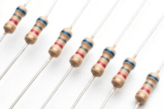
Figure 1. Carbon Film Resistors
What is Carbon Film Resistors?
A Carbon Film Resistor is a type of fixed resistor used to control electrical current or divide voltage in electronic circuits. It is made by applying a thin layer of carbon onto a ceramic insulating core. The carbon layer acts as the resistive element, restricting the flow of current through the component.
Carbon film resistors are available in a wide range of resistance values, typically from a few ohms to several megaohms. Their tolerance levels generally range from ±2% to ±10%, making them suitable for general-purpose applications.
Carbon Film Resistor Construction
Carbon film resistors are formed by coating a ceramic core with a thin layer of carbon. The construction of a carbon film resistor consists of the following five main parts, as shown in the image:

Figure 2. Carbon Film Resistor Construction
Ceramic Substrate
The ceramic substrate forms the core of the resistor. It is chosen for its excellent insulating properties and ability to withstand high temperatures. This substrate provides a stable foundation and prevents heat or electricity from affecting other circuit components.
Carbon Film
A thin layer of carbon is deposited on the ceramic surface. This carbon film acts as the resistive element, limiting the flow of electrical current through the resistor. The resistance value can be adjusted by modifying the thickness of the carbon layer or cutting a spiral groove into it.
End Caps
Metal end caps are fitted on both ends of the resistor. They ensure secure electrical contact with the carbon film and provide mechanical support for the connecting leads.
Connecting Leads
Copper connecting leads extend from each end cap. These leads allow the resistor to be easily connected within an electronic circuit.
Epoxy Layer
The entire assembly is coated with an epoxy layer. This coating protects the resistor from physical damage, moisture, and dust, while also maintaining its long-term stability in various environmental conditions.
The carbon film resistor ceramic core ensures insulation, the carbon film provides resistance, and the end caps with connecting leads facilitate circuit integration. The protective epoxy layer further enhances the component's stability. This construction allows the resistor to achieve a wide range of resistance values.
Carbon Film Resistor Working Principle
Carbon film resistors work by using a thin carbon layer deposited on a ceramic substrate as the resistive element. The carbon film resists the flow of electric current, while the ceramic base provides insulation and thermal stability.
To create this film, hydrocarbons such as methane are thermally decomposed at around 1000 °C in a vacuum, allowing carbon to adhere to the ceramic surface. A helical groove is then cut into the carbon film, increasing the path length of the current, which allows precise control of the resistance value. The resistance can be fine-tuned by adjusting the thickness of the carbon layer or the geometry of the groove.
Parameters of Carbon Film Resistors
Nominal Resistance Value
The nominal value is the labeled resistance of the resistor. It is measured in ohms (Ω) and often expressed in larger units such as kiloohms (KΩ) or megaohms (MΩ). The unit conversion is simple:
• 1 KΩ equals 1,000 Ω
• 1 MΩ equals 1,000 KΩ
Carbon film resistors follow standardized resistance values based on international specifications. Their typical resistance range spans from 1 Ω to 10 MΩ.
Tolerance (Allowable Error)
Tolerance indicates how much the actual resistance can vary from the nominal value. This variation is expressed as a percentage and helps determine the resistor’s precision. Tolerance is usually marked by a letter code:
• F for ±1%
• G for ±2%
• J for ±5%
• K for ±10%
Lower tolerance means greater accuracy. For circuits that require precise voltage or current control, resistors with tighter tolerances are recommended.
Rated Power
Rated power is the maximum amount of power a resistor can safely dissipate without affecting its performance. It is measured in watts (W) and depends on factors like ambient temperature and airflow. Although power ratings are not printed on the resistor body, they can be estimated based on the component’s size. Larger resistors typically support higher power ratings. Common rated power levels include:
• 0.125 W, 0.25 W, 0.5 W, 1 W, 2 W, 5 W, 10 W
For compact electronics, smaller carbon film resistors like the RTX series are used. These resistors are color-coded and usually rated at 0.125 W.
Tolerance Grades and Error Rates
Carbon film resistors are categorized by error rate into three standard levels:
• Grade 1: ±5%, Grade 2: ±10%, Grade 3: ±20%
Most general-purpose resistors fall within the 5% to 10% range. Choosing the right grade depends on the accuracy required in your circuit.
Carbon Film Resistor Markings
Carbon film resistors are often labeled with an “RT” code:
• R stands for resistor, T indicates the carbon film material
For example, RT47kJ refers to a carbon film resistor with a resistance of 47 KΩ and a ±5% tolerance.
Carbon film resistors are marked in several ways.

Figure 3. Direct Marking Method on Carbon Film Resistor
The Direct Marking Method shows the resistance value and unit directly on the resistor; if no tolerance is noted, it is ±20%. The Text Symbol Method uses numbers and letters-numbers indicate the value, and letters show decimal placement and tolerance. The Digital Method uses three digits: the first two are significant figures, and the third is the number of zeros. Tolerance is shown with a letter. The Color Code Method, which will be explained next, uses colored bands to represent values and tolerance.
Carbon Film Resistor Color Code
Carbon film resistors use a standardized color-coding system to indicate their resistance value, tolerance, and sometimes temperature coefficient. The code is represented by a series of colored bands printed on the resistor's body. Each color corresponds to a numerical value or multiplier, as shown in the table provided.
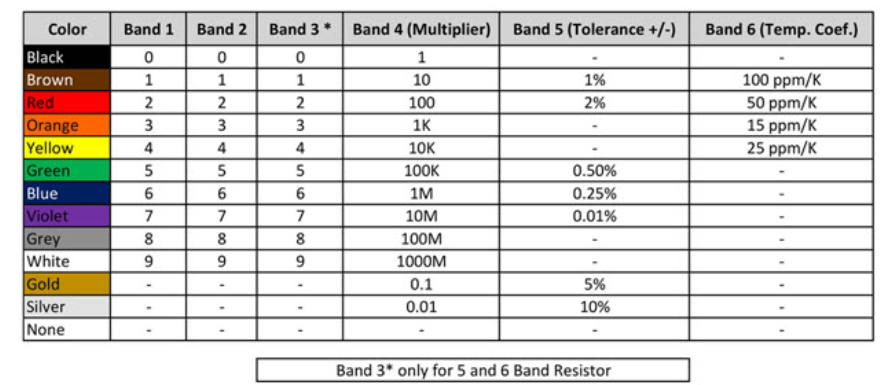
Figure 4. Carbon Film Resistor Color Code
Bands Meaning:
• Band 1 & 2 – First and second significant digits.
• Band 3 – Third digit (only for 5- and 6-band resistors).
• Band 4 – Multiplier (power of ten).
• Band 5 – Tolerance (accuracy of value).
• Band 6 – Temperature coefficient (change with temperature, only for 6-band).
Color Values:
• Digits: Black (0), Brown (1), Red (2), Orange (3), Yellow (4), Green (5), Blue (6), Violet (7), Grey (8), White (9)
• Multipliers: Same colors as digits, Gold (0.1), Silver (0.01)
• Tolerance: Brown (±1%), Red (±2%), Gold (±5%), Silver (±10%), None (±20%)
• Temp. Coefficient: Brown (100 ppm/K), Red (50 ppm/K), Orange (15 ppm/K), Yellow (25 ppm/K)
Example:
Colors: Red, Violet, Yellow, Gold -> 27×10,000=270kΩ27 × 10,000 = 270kΩ27×10,000=270kΩ ±5%.
Technical Specifications of Carbon Film Resistors
|
Parameter |
Typical
Specification |
|
Resistance Range |
1 Ω to 10 MΩ |
|
Tolerance Options |
±1%, ±2%, ±5%, ±10%, ±20% |
|
Load Life Stability |
≤ ±2% change after 1000 hours at rated
load |
|
Maximum Noise Level |
≤ 20 µV/V |
|
Temperature Coefficient (TCR) |
±200 ppm/°C to ±1500 ppm/°C |
|
Voltage Coefficient |
0.0005 %/V |
|
Maximum Operating Temperature |
150 °C |
|
Power Rating |
0.125 W to 2 W (depending on size) |
|
Dielectric Withstanding Voltage |
Typically, 300 V to 700 V |
|
Insulation Resistance |
≥ 10⁹ Ω |
|
Operating Temperature Range |
-55 °C to +155 °C |
|
Failure Rate |
< 1 failure per 10⁶ hours |
|
Environmental Protection |
Coated with epoxy or similar protective
material |
|
Compliance |
Meets RoHS, REACH, and IEC standards |
Applications of Carbon Film Resistors
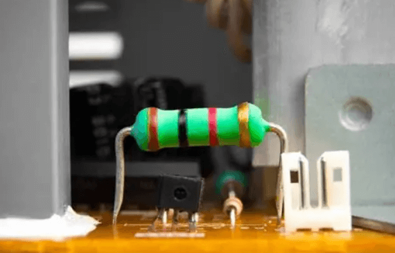
Figure 5. Carbon Film Resistors Uses
• High-Voltage Power Supplies – Carbon film resistors are ideal for circuits requiring resistance to voltages up to 15 kV.
• Radar and Communication Systems – Withstands high-frequency and heat-intensive environments.
• X-ray and Medical Imaging Equipment – Carbon film resistors operate reliably under elevated temperatures and electrical stress.
• Laser Technologies – Suitable for circuits exposed to extreme heat and power surges.
• Consumer Electronics – Commonly used in televisions, radios, and audio devices for signal stability.
• Automotive Electronics – Carbon film resistor supports performance in engine control units (ECUs) and other heat-prone automotive circuits.
• Industrial Machinery – Provides durability in power regulators, motor controls, and automation systems.
• Measurement and Test Instruments – Ensures accuracy in precision equipment exposed to varied temperatures.
• Power Conversion Systems – Carbon film resistors are used in inverters, UPS, and other systems where high voltage stability is required.
• Aerospace and Defense Applications – Critical for systems exposed to harsh environments and demanding operational conditions.
Carbon Film Resistors Advantages and Drawbacks
|
Features |
Advantages |
Disadvantages |
|
Temperature Stability |
Stable resistance across changing
temperatures |
Less stable than metal film resistors in
extreme thermal conditions |
|
Noise Performance |
Low electrical noise, ideal for audio
and precision circuits |
Still noisier than metal film
alternatives |
|
Cost and Availability |
Inexpensive and widely available |
Lower performance compared to
higher-grade resistors |
|
Manufacturing Precision |
Easy to fine-tune resistance using laser
trimming |
Limited to standard tolerance ranges
(±2% to ±10%) |
|
Durability |
Epoxy coating protects against moisture
and damage |
Less durable in high-humidity or
corrosive environments |
|
Resistance Range |
Offers a wide resistance range (1Ω to
10MΩ) |
Limited performance at high frequencies |
|
Power Handling |
Supports common power ratings (1/8W to
2W) |
Not suitable for high-power or
high-precision applications |
|
General Use |
Reliable for most standard, non-critical
electronic applications |
Not recommended for mission-critical or
highly sensitive electronics |
Carbon Film Resistor vs. Other Resistor
Metal Film Resistor VS. Carbon Film Resistor
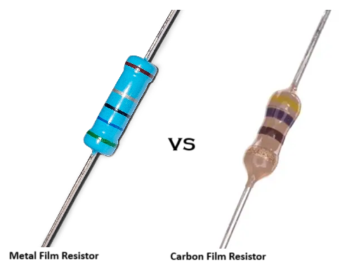
Figure 6. Metal Film Resistors and Carbon Film Resistors
|
Feature
|
Metal
Film Resistor |
Carbon
Film Resistor |
|
Material |
Thin metal layer (usually
nickel-chromium alloy) deposited on a ceramic rod. |
Carbon film deposited on a ceramic
substrate. |
|
Construction |
Metal film is precisely trimmed (spiral
cut) to set resistance. |
Carbon film is deposited and shaped to
form resistance. |
|
Tolerance |
Very tight tolerance, typically ±0.1% to
±1%. |
Higher tolerance, typically ±2% to ±5%. |
|
Temperature Coefficient |
Low (±50 to ±100 ppm/°C), stable with
temperature changes. |
Higher (±200 to ±500 ppm/°C), less
stable with temperature. |
|
Noise Level |
Very low noise due to uniform metal
film. |
Higher noise because of granular carbon
composition. |
|
Stability & Reliability |
Highly stable over time and
environmental conditions. |
Less stable; can drift with age and
environmental changes. |
|
Resistance Range |
Wide range: typically from a few ohms to
several MΩ. |
Moderate range: typically from a few
ohms to a few MΩ. |
|
Power Rating |
Generally lower power rating compared to
carbon film of similar size. |
Slightly higher power rating for the
same size. |
|
Frequency Response |
Excellent for high-frequency
applications (low inductance and capacitance). |
Not as good at high frequencies; higher
inductance. |
|
Temperature Stability |
Very good – minimal change with
temperature variation. |
Poorer – resistance can vary
significantly with temperature. |
|
Voltage Coefficient |
Very low; resistance remains stable
under voltage. |
Higher; resistance can change with
applied voltage. |
|
Durability |
More sensitive to surge and overload
conditions. |
Better tolerance to overloads and
surges. |
|
Cost |
More expensive due to precision
manufacturing. |
Cheaper, widely used for general
purposes. |
|
Applications |
Precision circuits, low-noise
amplifiers, measurement instruments, high-frequency uses. |
General-purpose electronics, consumer
devices, applications where precision is not critical. |
|
Color Code |
Standard resistor color code used. |
Standard resistor color code used. |
|
Typical Sizes |
Available in standard through-hole and
SMD packages. |
Also available in standard through-hole
and SMD packages. |
|
Lifespan |
Longer lifespan in stable operating
conditions. |
Shorter lifespan compared to metal film,
especially under stress. |
|
Common Wattage Ratings |
1/8W, 1/4W, 1/2W, 1W (typically lower
for precision types). |
1/4W, 1/2W, 1W, 2W (can handle slightly
more power). |
Carbon Composition Resistor VS. Carbon Film Resistor
While both serve the same basic function of limiting current and controlling voltage, they differ in construction, performance characteristics, stability, and applications.
|
Feature |
Carbon
Composition Resistor (CCR) |
Carbon
Film Resistor (CFR) |
|
Construction |
Made from a mixture of carbon powder and
a binding resin, molded into a solid cylindrical body. |
Made by depositing a thin carbon film on
a ceramic substrate. |
|
Manufacturing Process |
Carbon particles are mixed with a
binder, pressed, and baked. |
Carbon film is deposited (usually via
chemical vapor deposition) and spiral-cut to adjust resistance. |
|
Resistance Range |
Typically 1 Ω to 22 MΩ |
Typically 1 Ω to 10 MΩ |
|
Tolerance |
Poor (±5% to ±20%) |
Better (±1% to ±5%) |
|
Temperature Coefficient |
High (resistance varies significantly
with temperature) |
Lower than CCR (more stable with
temperature changes) |
|
Noise Level |
High (generates more electrical noise) |
Low (less noise due to uniform film
structure) |
|
Stability |
Less stable over time and with
environmental conditions |
More stable and reliable over long
periods |
|
Power Rating |
Can handle short bursts of high energy
(surge capability) |
Lower surge handling capability |
|
Size |
Larger for a given resistance and power
rating |
Smaller and more compact |
|
Cost |
Usually more expensive to produce |
Generally cheaper than CCR |
|
Lifespan |
Shorter due to drift and degradation |
Longer lifespan due to stable
construction |
|
Frequency Response |
Poor at high frequencies |
Better high-frequency performance |
|
Current Use |
Rarely used in modern electronics,
mainly for specific surge applications |
Commonly used in most electronic devices
today |
Conclusion
Carbon film resistors offer a good balance of performance and reliability. They provide low noise, stable resistance, and can handle a range of temperatures. Although they are less precise than metal film resistors and not as durable as some other types, they are still an excellent choice for standard applications. Their simple construction and protective coating ensure long-term operation. Making them a trusted component in many electrical and electronic systems.
function test. The highest cost-effective products and the best service is our eternal commitment.
Hot Article
- LM358 Dual Operational Amplifier Comprehensive Guide: Pinouts, Circuit Diagrams, Equivalents, Useful Examples
- Are CR2032 and CR2016 Interchangeable?
- Understanding the Differences ESP32 and ESP32-S3 Technical and Performance Analysis
- Choosing the Right Battery: A Guide to AG4, LR626, LR66, 177/376/377, SR626, and SR626SW Equivalents
- BC547 Transistor Basics: Pinout, Application Circuits, Alternative/Complementary Models
- NPN vs. PNP: What's the Difference?
- esp32 vs stm32: which microcontroller is better for you?
- What Is a MOSFET and How It Works?
- Electrical Relay Basic: Working Operation, Types and Uses
- PNP Transistors: Structure, Working Principle and Application
 Basics of Dipole Antennas: Types, Applications, Installation Tips
2024-09-02
 Basic Principles of RF / Microwave Circulators / Isolators
2025-08-06
Frequently Asked Questions [FAQ]
1. How do carbon film resistors differ from wire-wound resistors?
Carbon film resistors use a thin carbon layer for resistance, while wire-wound resistors use a coiled metal wire. Wire-wound types handle higher power and have lower noise, but they are bulkier and more expensive.
2. What causes carbon film resistors to fail?
Failure typically occurs due to overheating, prolonged exposure to high humidity, voltage surges, or physical damage to the epoxy coating, leading to resistance drift or open circuits.
3. How to test a carbon film resistor with a multimeter?
Set the multimeter to the resistance (Ω) mode, connect probes to both leads, and compare the reading with the resistor’s marked or color-coded value. A large deviation indicates damage or drift.
4. Do carbon film resistors have a maximum voltage rating?
Yes, each resistor has a maximum working voltage-usually between 200V and 700V depending on size. Exceeding this can cause arcing or permanent damage.
5. Can carbon film resistors replace metal film resistors?
They can replace metal film resistors in non-critical circuits, but they offer lower precision, higher noise, and less stability. Making them unsuitable for high-accuracy or low-noise applications.
Hot Part Number
 CX0805MRX7R8BB223
 CGA2B2X8R1H152M050BE
 08055U101KAT4A
 CC0603JRX7R8BB224
- 08055U5R6BAT2A
 06035U5R6CAT2A
 12065C105JAT2A
 GRM1886S1HR90CD01D
 TBJD476K016LSSB0023
 BDW84C
- X1205S8I
- VE-220-IY
- VI-JWB-MZ
- KP236N6165XTMA1
- MCC40-10I08
- T491D336K025ATAUTO7280
- TRSF3243CPWR
- AM5728BABCXEA
- LC75833W-TBM-E
- UCC2892PWR
- CDC337DWR
- T491C475K025AT2478
- TPS2044BD
- STM32L071RBT6TR
- TPS5410MDREP
- TS5A22364DGSR
- ADT7421ARMZ
- AK4340ET
- ATD97SC3202-X1AC
- CS5532ASZ
- CY14E256LA-SZ25X
- HD155141
- LM4880MX
- M60089H-0201Y
- MB89615-150
- S-93C56BD0I-T8T1GE
- VT261WFQR-ADJ
- MIP2K40MSSCF
- IC41C16100S-50K
- LV1605ML-MPB-E
- PSN76025A0
- BQ40Z80RSMT
- VT1622AG
- ANA37326B
- AND0241RM27Q7
- CXD2913AQ
- CY7C1382D-200BZXC
- GD25Q64CFIG
- RGTVX6TS65DGC11