What Is a Rectifier Diode and How Does It Work?
2025-10-13
10756
Catalog
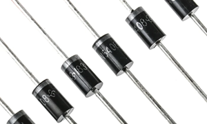
Figure 1. Rectifier Diodes
What is a Rectifier Diode?

Figure 2. Rectifier Diode Symbol and Terminals
A Rectifier Diode is a semiconductor device that change alternating current (AC) into direct current (DC). It’s one of the main components found in rectifier circuits, such as half-wave or bridge rectifiers, that supply DC power to electronic devices.
Most rectifier diodes are made from silicon (Si) since it can handle high current and voltage levels efficiently. Some are also made from germanium (Ge) or gallium arsenide (GaAs) for special applications. Germanium diodes have a lower forward voltage drop, which means they can start conducting at smaller voltages, but they can’t withstand as much heat or reverse voltage as silicon types.
Rectifier diodes are described by two main sets of parameters: maximum ratings (like allowable current, voltage, and temperature) and electrical characteristics (such as forward voltage and reverse recovery time). The circuit symbol of a rectifier diode includes an arrow that points in the direction of conventional current flow, from the anode to the cathode.
How a Rectifier Diode Works
Rectifier Diode works by letting electricity flow in only one direction. Rectifier diode allows current to pass from the anode to the cathode, but blocks it from going the other way. This simple action helps turn alternating current (AC) into direct current (DC).
When the diode is connected to AC source, it let current to flow only during the positive half of the cycle and blocks it during the negative half. This process, called rectification, changes AC into a one-way current known as pulsating DC.
Sometimes, more than one diode is used to get a smoother and stronger DC output. A half-wave rectifier uses one diode, while a full-wave or bridge rectifier uses four diodes to use both halves of the AC signal. To make the DC output more stable, capacitors or voltage regulators are added. They help remove the small ripples in the current, giving a smooth DC supply for electronic devices.
Unbiased Rectifier Diode
An unbiased rectifier diode is a diode that has no voltage applied to it. This means it is not connected to any power source or bias. In this state, the diode is inactive and does not let current flow. Inside the diode, there is a small region called the depletion layer that naturally blocks current. When there is no external voltage, this layer stays the same, and the diode acts like an open circuit. For example, if the voltage across the diode is less than 0.7 volts (for silicon diodes) or 0.3 volts (for germanium diodes), it will not conduct electricity. Once a forward voltage is applied and goes above that level, the diode starts to conduct and allows current to flow in one direction.
Forward Biased Diode
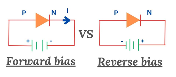
Figure 3. Forward Bias vs Reverse Bias of a Diode
A Forward biased diode means the positive side of the battery is connected to the anode (P-side) of the diode, and the negative side is connected to the cathode (N-side). In this way, the diode lets electricity flow through it.
The voltage from the battery lowers the resistance inside the diode, making it easier for electric charges to move. When the voltage reaches about 0.7 volts for silicon diodes or 0.3 volts for germanium diodes, the diode turns on and allows current to flow in one direction.
Reverse Biased Diode
A Reverse biased diode is connected in the opposite direction of a forward-biased one. The positive side of the battery is connected to the cathode (N-side), and the negative side is connected to the anode (P-side).
In this condition, the diode does not conduct current. The region between the P and N sides, called the depletion layer, becomes wider, which increases resistance and stops current from flowing. Only a very small current, known as leakage current, may pass through.
If the reverse voltage becomes too high, the diode can break down, allowing current to flow and possibly causing damage.
Half-Wave and Full-Wave Rectifier Operation
There are two main types of rectifiers, half-wave and full-wave. They work in different ways depending on how much of the AC signal they use and how smooth their DC output is.

Figure 4. Bridge Rectifier Circuit Diagram
Half-Wave Rectifier
A half-wave rectifier uses one diode to make one half of the AC waveform (usually the positive half) to pass through while blocking the other half. This process turns AC into a pulsating DC output. Since the half-wave rectifier uses only one half of the AC signal, it is less efficient, about 40% compared to a full-wave rectifier. The output is uneven, so capacitors are added to make the voltage smoother.
Although half-wave rectifiers are less efficient, they are simple, affordable, and found in small devices or signal detection circuits where high efficiency isn’t needed.
Full-Wave Rectifier
A full-wave rectifier converts both halves of the AC signal into DC, giving a smoother and more efficient output. It can be built in two ways:
• Center-Tapped Full-Wave Rectifier - Uses a center-tapped transformer and two diodes. Each diode conducts during one half of the AC cycle.
• Bridge Rectifier - Uses four diodes arranged in a bridge setup. This design doesn’t need a center-tapped transformer and is widely seen in modern power supplies.
Parameters of Rectifier Diodes
Rectifier diodes have some main parameters that define how they work and how much power they can handle. By looking at things like recovery time, voltage limit, and current capacity, you can pick the right diode for different uses, such as power supplies or signal circuits. These parameters help rectifier diodes safely and efficiently convert AC (alternating current) into DC (direct current), providing a steady and reliable flow of electricity in electronic devices. Knowing these limits helps the diode work better and last longer.
Temperature Limits of Rectifier Diodes
Rectifier diodes must operate within a safe temperature range to work properly. When the temperature becomes too high, the diode’s internal parts can weaken, causing poor performance or even permanent damage. During normal operation, diodes generate heat, especially in high-power circuits where large amounts of current flow. To control this heat, cooling methods such as heat sinks or fans are required. If a diode overheats, its efficiency drops, and it may fail gradually. Keeping it within the right temperature range helps it work well, last longer, and stay reliable.
High-Current Capacity of Rectifier Diodes
High-current capacity is one of the most important features of a rectifier diode. It shows how much electric current the diode can handle while still working safely and efficiently. High-current diodes are built with materials and structures that minimize voltage drop and reduce heat generation during operation. These improvements help maintain stable performance even under heavy electrical loads.
Types of Rectifier Diodes
Rectifier diodes are available in various type, each designed for specific electrical tasks. They differ in how much voltage, current, and switching speed they can handle. Below are the common types used in various circuits:
General-Purpose Rectifier Diode - Used in power supplies and AC to DC converters, this type handles moderate current and voltage levels. It is reliable for basic electronic equipment.Example: 1N4001–1N4007 series
Fast Recovery Diode - This diode can switch on and off very quickly, making it suitable for high-frequency circuits such as inverters, switching power units, and motor drives.
Schottky Diode - Made with a metal-semiconductor junction, it has a low forward voltage drop (around 0.2–0.3 V) and high switching speed. It’s ideal for low-voltage and energy-efficient applications like DC-DC converters.
High-Current Diode - Built for large current loads, this type is used in industrial systems, battery chargers, and motor controllers. Its sturdy construction allows effective heat dissipation and stable performance.
Bridge Rectifier – Bridge rectifier uses four diodes arranged in a bridge circuit to convert AC into DC on both half cycles. It provides a smoother output and is common in adapters, chargers, and DC power modules.
Testing a Rectifier Diode with Multimeter
Testing a rectifier diode is an easy way to check if it’s working properly. You can do this using a digital multimeter (DMM) with two test leads, one red and one black.
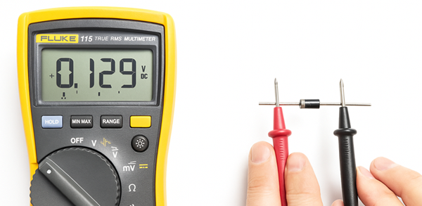
Figure 5. Testing a Diode with a Multimeter
Steps:
• Make sure the power is off before testing
• Turn the multimeter dial to the Diode Test setting (look for a diode symbol)
• Find the diode’s anode (+) and cathode (–). The cathode usually has a band or stripe
• Connect the red probe to the anode and the black probe to the cathode
• A working diode will show a reading between 0.5–0.7 V for silicon diodes or 0.3 V for germanium types
• Now switch the wires (red to the cathode, black to the anode). The display should show OL or no reading, meaning the diode is blocking current properly
• If you see a reading both ways or nothing at all, the diode is bad and should be replaced
Diode Testing with an Ohmmeter
You can also check if a diode works by using the ohm (Ω) setting on a multimeter. This test shows how much the diode resists the flow of electricity.
Steps:
• Turn-off the device before you start
• Turn the multimeter to the ohm (Ω) or resistance mode
• Find the diode’s two ends, the anode (+) and the cathode (–). The cathode has a stripe
• Touch the red probe to the anode and the black probe to the cathode
- You should see a low number, this means the diode allows current to pass
• Now switch the probes (red to cathode, black to anode)
- The screen should show a high number or OL, this means the diode is blocking current
Testing a Diode Using Voltage Measurement Mode
The VDC setting on a multimeter can also check the voltage drop across a diode.
Steps:
• Turn the dial to VDC mode
• Plug red into VΩmA and black into COM
• Select a voltage range higher than expected
• Connect red to anode, black to cathode, and read the value
• Swap the probes to check the opposite direction
Applications of Rectifier Diodes
Phone and Laptop Chargers - Rectifier diodes change the AC from a wall outlet into DC that your phone, laptop, or power bank needs to charge safely.
Power Supplies - Used in radios, TVs, computers, and amplifiers, they help make a steady DC power output from AC so devices can run smoothly.
Motor Control Systems (VFDs) - In factories and machines, diodes are used in Variable Frequency Drives (VFDs) to control the speed and power of electric motors.
Bridge Rectifiers - A bridge rectifier is made of four diodes connected together. It changes both halves of the AC signal into DC and is found in battery chargers and adapters.
Radios and Signal Circuits - In radio receivers, rectifier diodes help pick up and separate sound signals from the radio waves so you can hear them clearly.
Protection Circuits - Rectifier diodes keep current from flowing the wrong way. They are used in solar panels, car alternators, and control boards to protect parts from damage.
Air Conditioners and Heating Systems (HVAC) - Used in control boards of air conditioners and heaters to manage signals and power flow inside the system.
Transformers and Power Systems - In power converters and transformers, diodes help change high-voltage AC into low-voltage DC for industrial tools and machines.
LED Lights - Rectifier diodes provide stable DC power to LED bulbs so they shine evenly without flickering.
Welding Machines - In arc welders and industrial tools, they help create steady DC current, which makes the welding arc smooth and strong.
How to Choose the Right Rectifier Diode
Choosing the right rectifier diode is important to make sure your circuit works safely and efficiently. Here’s an easy guide to help you pick the right one:
Check the Maximum Current (IF) - Find out how much current your circuit will use. Choose a diode that can handle at least 20–30% more than the expected current.
Example: If your circuit uses 2A, choose a diode rated for 3A or more.
Check the Reverse Voltage (VR or PIV) - This is the maximum voltage the diode can block when reverse-biased. Pick one with a voltage rating higher than the maximum AC voltage in your circuit.
Example: For 50V AC, use a diode rated for 100V or more.
Look at the Forward Voltage Drop (VF) - A lower forward voltage drop means less power loss and better efficiency.
• Silicon diodes: about 0.7V drop
• Schottky diodes: about 0.3V drop (good for low-voltage circuits)
Check the Reverse Recovery Time - If you’re working with high-speed or switching circuits, choose a diode with a short recovery time (like a fast recovery or Schottky diode) to handle quick signal changes.
Consider Power Dissipation - Make sure the diode can handle the heat it produces. If your circuit runs at high current, use a heat sink or pick a diode rated for higher power.
Environment and Size - Think about where the diode will be used. For hot or industrial environments, use one that can handle higher temperature limits. Also, check if the diode’s package size fits your circuit board.
Application Type
• For general circuits: Use 1N4001–1N4007series
• For fast switching: Use 1N4148 or similar
• For high current: Use diodes like 6A10 or bridge rectifiers
• For low-voltage, high-efficiency circuits: Choose Schottky diodes
Conclusion
Rectifier diodes are used in almost all electrical devices. They help change, control, and protect the flow of electricity so everything runs smoothly. Learning how they work and how to choose the right one can help you fix or build simple circuits.
function test. The highest cost-effective products and the best service is our eternal commitment.
Hot Article
- LM358 Dual Operational Amplifier Comprehensive Guide: Pinouts, Circuit Diagrams, Equivalents, Useful Examples
- Are CR2032 and CR2016 Interchangeable?
- Understanding the Differences ESP32 and ESP32-S3 Technical and Performance Analysis
- Choosing the Right Battery: A Guide to AG4, LR626, LR66, 177/376/377, SR626, and SR626SW Equivalents
- BC547 Transistor Basics: Pinout, Application Circuits, Alternative/Complementary Models
- NPN vs. PNP: What's the Difference?
- esp32 vs stm32: which microcontroller is better for you?
- What Is a MOSFET and How It Works?
- Electrical Relay Basic: Working Operation, Types and Uses
- PNP Transistors: Structure, Working Principle and Application
 Understanding 555 Timer PWM Motor Speed Control in Simple Terms
2025-10-13
 The Ultimate Soldering Guide: Master Tools, Techniques, and Temperature
2025-10-11
Frequently Asked Questions [FAQ]
1. What is the difference between a diode and a rectifier?
A diode is a semiconductor device that lets current flow in one direction, while a rectifier is a circuit that uses one or more diodes to change AC into DC. In short, a rectifier is built from diodes and performs current conversion.
2. Can I use any diode as a rectifier?
Not all diodes can be used as rectifiers. Only rectifier diodes are designed to handle higher voltage and current levels safely. Small-signal diodes, for example, are better for low-power or signal applications rather than power conversion.
3. Can a rectifier diode convert DC back to AC?
No. A rectifier diode only lets electricity flow in one direction, so it cannot turn DC into AC. To do that, an inverter circuit is needed, which works in the opposite way of a rectifier.
4. How do I know which side of a diode is positive?
The anode is the positive side, and the cathode is the negative side. You can identify the cathode by a small stripe or band printed on the diode’s body, showing the direction that current should flow toward.
5. Can I use multiple diodes together?
Yes. You can connect diodes in series to handle higher voltage or in parallel to handle more current. However, matching their ratings is important to ensure they share the load evenly and work safely.
Hot Part Number
 CS242C001PZ-TRSV
 APA600-PQ208
 UCC3818N
 SI8233AD-D-IS
 AD5262BRUZ20-RL7
 MC9S12XA512VAL
 MC14040BDTR2G
 GRM1886S1H1R1CZ01D
 GRM0225C1E4R1CDAEL
 INA240A2PW
- T491D107K006ZT7280
- UMK316B7474ML-T
- MT47H64M8CF-25E:G
- 08051U150GAT2A
- RT0402DRD072K49L
- VLF4012AT-100MR79
- C2012X5R0J225K085AA
- IXFP22N65X2M
- GMOV-14D500K
- 5SGXMABK2H40I2N
- C1608X7R1E474K080AB
- T495D476K010ATE080
- MAX8860EUA27
- CY8C20140-SX2I
- LT3971AIMSE#PBF
- LT1999CMS8-50F#PBF
- CC0603ZRY5V6BB474
- SN74LVC32ADR
- IS42S16160B-6TL
- TPSE106M050R0500
- SKM150GAL128D
- ATMXT1666T2-C2U
- BU20360-48L
- ICS950218AFT
- MAX1779EUE+TG104
- MAX202ECWE-T
- G5LA-1A4-12V
- HN29V256AOBBP-30
- M66445M1FA
- NFP-2200-A3
- PCD8010H/E31/4
- PEAD22653AFV1QH14NAR
- 6MBP150RTM060
- S29GL032A90FAIR43
- TMR3-1211
- T6TD7XBG-0001
- IBMPPCBWY-GES72914
- SDINBDG4-8G-XI1
- XFL4020-332MEC