What Is a Half Wave Rectifier?
2025-12-26
3305
Catalog
Understanding the Half Wave Rectifier
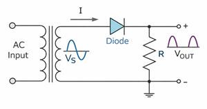
A half wave rectifier is an electronic circuit that converts alternating current (AC) into direct current (DC) by allowing current to flow during only one half of the input AC cycle. It uses a single diode, which conducts during one half cycle and blocks current during the opposite half cycle. As a result, the output is a unidirectional DC voltage with ripple.
Because it has a simple design and uses very few components, the half wave rectifier is mainly used for learning purposes and in low-power circuits where high efficiency and smooth output are not important.
Operation of a Half Wave Rectifier
When an AC voltage is applied to the rectifier circuit, the diode operates based on the polarity of the input voltage.
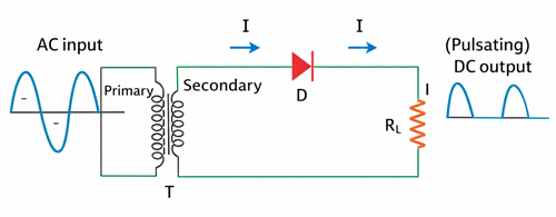
Figure 2. Positive Half Cycle Operation
Positive Half Cycle
During the positive half cycle of the AC input, the diode is forward biased. Current flows from the transformer secondary through the diode and load resistor, producing a positive voltage across the load.
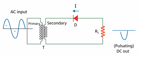
Figure 3. Negative Half Cycle Operation
Negative Half Cycle
During the negative half cycle, the diode becomes reverse biased. Current flow stops, and the output voltage across the load drops to zero.

Figure 4. Output Waveform of a Half Wave Rectifier
Output Waveform
This alternating conduction and blocking action produces an output waveform consisting of positive voltage pulses separated by zero-voltage intervals, resulting in pulsating DC.
Circuit Behavior
The circuit behaves as a closed loop during the conducting half cycle and as an open circuit during the blocked half cycle, which directly determines the shape of the output waveform.
Purpose of Half Wave Rectification

Figure 5. Converting AC into Usable DC
Most electronic circuits need DC voltage to work properly, and using AC directly can damage DC components. A half wave rectifier converts AC into unidirectional DC, making it suitable for low-power applications. The input voltage is sinusoidal AC, but after rectification only one half of the waveform appears across the load. The output keeps a single polarity but changes in size, so it is called pulsating DC with ripple. Even though this output is not smooth or highly efficient, it is acceptable where simple design and low cost are more important than high efficiency and smooth output.
Components of a Half Wave Rectifier
Transformer: Steps the AC voltage up or down to the required level.
Diode: Controls the direction of current flow.
Load resistor: Receives the rectified output voltage.
Types of Half Wave Rectifier
Positive half wave rectifier: Allows positive half cycles to pass.
Negative half wave rectifier: Allows negative half cycles to pass.
The operating principle remains the same. Only the diode orientation is reversed.
Filtering in a Half Wave Rectifier
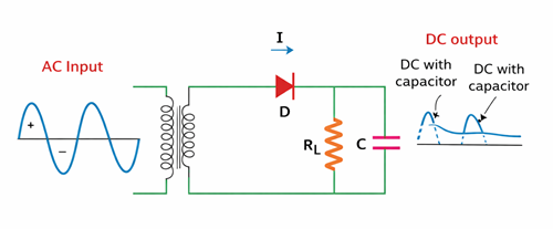
Figure 6. Filtering in a Half Wave Rectifier
Adding a capacitor filter improves the quality of the rectified output by reducing ripple. The capacitor charges during the peak of the conducting half cycle and discharges through the load when the input voltage decreases.
The effectiveness of ripple reduction depends on:
• The value of the filter capacitor
• The load resistance
Larger capacitance and higher load resistance result in smoother DC output.
Characteristics of Half Wave Rectifier
Peak Inverse Voltage (PIV)
Peak Inverse Voltage is the maximum reverse voltage that a diode must withstand. During the non-conducting half cycle, the entire secondary voltage appears across the diode.
Selecting a diode with an adequate PIV rating ensures reliable operation.
Important Formulas of Half Wave Rectifier
Ripple Factor (γ)
Ripple factor indicates the amount of AC content present in the rectified DC output.
For a half wave rectifier:
The high ripple factor shows that the output contains a large AC component, which explains the need for filtering.
Rectification Efficiency (η)
Efficiency represents how effectively the rectifier converts AC input power into DC output power.
Maximum theoretical efficiency for a half wave rectifier:
Low efficiency occurs because only one half of the AC input waveform is utilized.
Load Current
Let the peak current be Im.
Peak current:
Average (DC) current:
RMS current:
These values indicate the limited current and power-handling capability of the half wave rectifier.
Form Factor (F.F)
Form factor indicates the shape of the output waveform and its ripple content.
For a half wave rectifier:
Output DC Voltage
The average DC output voltage is given by:
where
The low DC output voltage limits the half wave rectifier to low-power applications.
Pros and Cons of Half Wave Rectifier
Pros
Simple circuit design
Low cost
Compact size
Suitable for low-power applications
Cons
Low efficiency
High ripple factor
Poor power utilization
Low DC output voltage
Where Half Wave Rectifier Is Used?
• Low-power rectification in simple power supplies
• Signal demodulation in AM radio receivers
• Peak detector circuits
• Education and laboratory demonstrations
Comparison of Half Wave and Full Wave Rectifier
|
Feature |
Half
Wave Rectifier |
Full
Wave Rectifier |
|
AC cycle used |
One half |
Both halves |
|
Number of diodes |
1 |
2 or 4 |
|
Average DC output |
0.318 Vm |
0.637 Vm |
|
Ripple factor |
High |
Low |
|
Efficiency |
Low |
High |
|
Output smoothness |
Poor |
Better |
|
Applications |
Low-power, education |
Power supplies, chargers |
Three Phase Half Wave Rectifier Explained
A three-phase half wave rectifier converts three-phase AC into DC using three diodes. Each diode is connected to one phase of the AC supply and conducts only when its phase voltage is the highest. At any given time, only one diode conducts, and each diode conducts for 120 degrees of the electrical cycle. The circuit typically uses a star-connected transformer secondary to provide a neutral path, and the outputs of all three diodes are combined to supply the load. The DC output contains ripple, but its ripple frequency is three times the supply frequency. For example, with a 50 Hz AC supply, the ripple frequency is 150 Hz. Compared to a single-phase half wave rectifier, the three-phase version provides a higher DC output, lower ripple, and better efficiency, although its performance is still lower than that of a three-phase full wave rectifier.
The average DC output voltage of a three-phase half wave rectifier is given by:
where Vm is the peak value of the phase voltage.
Conclusion
The half wave rectifier provides a simple method of AC to DC conversion but has limitations such as low efficiency and high ripple. Although filters and three-phase operation can improve performance, it is still inferior to full wave rectifiers. Despite this, it remains important for understanding rectification principles and diode behavior in electronic circuits.
function test. The highest cost-effective products and the best service is our eternal commitment.
Hot Article
- LM358 Dual Operational Amplifier Comprehensive Guide: Pinouts, Circuit Diagrams, Equivalents, Useful Examples
- Are CR2032 and CR2016 Interchangeable?
- Understanding the Differences ESP32 and ESP32-S3 Technical and Performance Analysis
- Choosing the Right Battery: A Guide to AG4, LR626, LR66, 177/376/377, SR626, and SR626SW Equivalents
- BC547 Transistor Basics: Pinout, Application Circuits, Alternative/Complementary Models
- NPN vs. PNP: What's the Difference?
- esp32 vs stm32: which microcontroller is better for you?
- What Is a MOSFET and How It Works?
- Electrical Relay Basic: Working Operation, Types and Uses
- PNP Transistors: Structure, Working Principle and Application
 A Simple Guide to Residual Current Circuit Breakers
2025-12-26
 Tantalum Capacitors: Types, Uses, Packaging and Features
2025-12-26
Frequently Asked Questions [FAQ]
1. Why is a half wave rectifier not used in high-power applications?
A half wave rectifier uses only one half of the AC cycle, which results in low efficiency, high ripple, and poor power utilization, making it unsuitable for high-power circuits.
2. What happens if the diode fails in a half wave rectifier?
If the diode fails open, the circuit stops producing output. If it fails short, AC may pass directly to the load, potentially damaging connected components.
3. Can a half wave rectifier work without a transformer?
Yes, it can work directly with an AC source, but a transformer is usually added for voltage adjustment and electrical isolation for safety.
4. How does frequency affect a half wave rectifier output?
Higher input frequency reduces the ripple magnitude for a given filter capacitor, resulting in smoother DC output compared to lower frequencies.
5. What type of diode is best for a half wave rectifier?
Silicon diodes are commonly used due to their higher efficiency, better temperature stability, and higher Peak Inverse Voltage ratings compared to germanium diodes.
6. Why does a half wave rectifier have high ripple?
Because it produces output only during one half of the AC cycle, the output voltage drops to zero during the other half, creating large fluctuations.
7. Can a half wave rectifier be used to charge batteries?
It can be used for very small, low-cost charging applications, but it is not recommended due to poor regulation and high ripple, which can reduce battery life.
8. How does load resistance affect a half wave rectifier?
Lower load resistance increases current but also increases ripple and diode stress, while higher load resistance improves output smoothness.
Hot Part Number
 C1608X7R1E474K080AB
 C2012X5R0J225K085AA
 GRM0225C1E4R1CDAEL
 CC0603ZRY5V6BB474
 UMK316B7474ML-T
 08051U150GAT2A
 GRM1886S1H1R1CZ01D
 T495D476K010ATE080
 TPSE106M050R0500
 APA600-PQ208
- MT47H64M8CF-25E:G
- MC9S12XA512VAL
- IS42S16160B-6TL
- SI8233AD-D-IS
- RT0402DRD072K49L
- CY8C20140-SX2I
- VLF4012AT-100MR79
- SKM150GAL128D
- MC100ELT21DR2G
- MC14040BDTR2G
- LT3971AIMSE#PBF
- T491D107K006ZT7280
- UCC3818N
- INA240A2PW
- IXFP22N65X2M
- LT1999CMS8-50F#PBF
- SN74LVC32ADR
- AD5262BRUZ20-RL7
- ATMXT1666T2-C2U
- BU20360-48L
- ICS950218AFT
- MAX1779EUE+TG104
- MAX202ECWE-T
- MAX8860EUA27
- G5LA-1A4-12V
- HN29V256AOBBP-30
- M66445M1FA
- NFP-2200-A3
- PCD8010H/E31/4
- PEAD22653AFV1QH14NAR
- 6MBP150RTM060
- S29GL032A90FAIR43
- TMR3-1211
- T6TD7XBG-0001
- CS242C001PZ-TRSV
- IBMPPCBWY-GES72914
- SDINBDG4-8G-XI1
- XFL4020-332MEC
- GMOV-14D500K