What Are Poles and Zeros in Transfer Functions?
2026-04-10
1069
Catalog
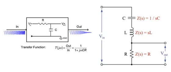
Figure 1. RC Circuit Transfer Function Example
What Is a Transfer Function?
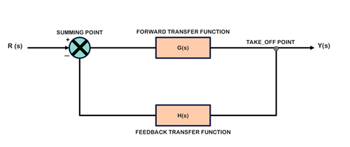
Figure 2. Feedback Control System Block Diagram
A transfer function is a mathematical representation that describes how a system or circuit transforms an input signal into an output signal, typically analyzed in the frequency domain. It is expressed as the ratio of the system’s output to its input using the complex variable s, which allows you to study system behavior beyond simple time-based analysis. The transfer function is written as:
Through this relationship, it becomes possible to evaluate how a system affects signal amplitude (gain) and phase across different frequencies. This makes it a basic tool in electronics and control systems, as it enables accurate prediction of circuit performance, analysis of stability, and deeper understanding of how poles and zeros influence overall system behavior.
What Are Poles and Zeros in Transfer Functions?
In a transfer function, poles and zeros are specific values of the complex variable s that determine how a system responds to different signals. A transfer function shows the relationship between the input and output of a system.
For example, consider the following transfer function:
In this expression, the numerator is Ks and the denominator is s + ω0.
A zero is a value of s that makes the numerator equal to zero. In this case, when s=0, the numerator becomes zero, so the system output becomes zero for certain inputs. This means signals at very low frequencies (near DC) are suppressed.
A pole is a value of s that makes the denominator equal to zero. Here, when s=-ω0, the denominator becomes zero, causing the system response to become very large. This strongly influences how the system behaves, especially around that frequency.
Understanding Poles and Zeros on the s-Plane
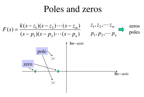
Figure 3. Poles and Zeros on the s-Plane
The s-plane is a simple way to visualize where poles and zeros are located and what they mean for a system. It is like a map, where each position shows how the system will behave. The horizontal line represents the actual part, and the vertical line represents the imaginary part.
When poles are placed on this map, their position tells us how the system responds. If a pole is close to the center (origin), the system changes slowly. If it is farther away, the system responds faster. When poles lie along the horizontal line, the system behaves smoothly without oscillation. But when they move away from that line, the system starts to show oscillations, which means the output can rise and fall in a wave-like way.
Another idea is stability. If all poles are on the left side of the s-plane, the system is stable and will settle over time. If any pole is on the right side, the system becomes unstable and its output can grow uncontrollably.
Zeros also appear on the s-plane and help shape how the system responds. They can reduce or cancel certain signals and adjust how the output looks. While poles control the main behavior of the system, zeros fine-tune the response.
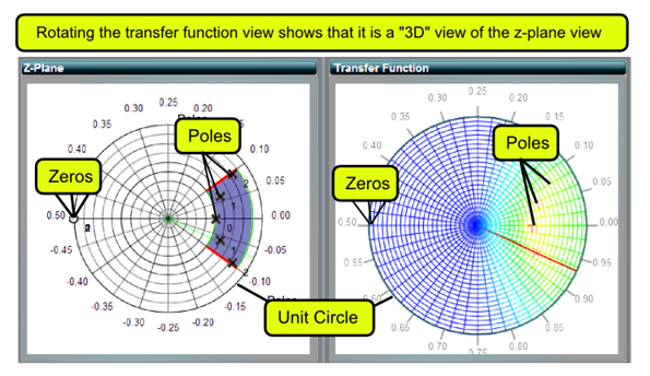
Figure 4. Pole-Zero Plot and Frequency Response (Z-Plane)
How Poles and Zeros Affect Frequency Response in Transfer Functions
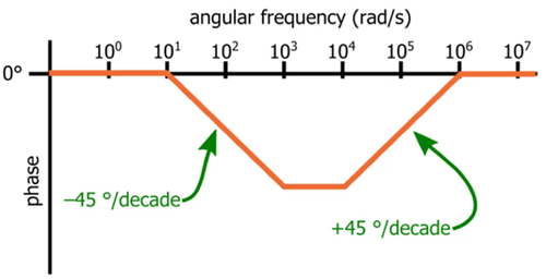
Figure 5. Bode Phase Plot Showing Pole-Zero Effect
Poles and zeros control how a system reacts to different frequencies. To study this, we look at the frequency response, which shows how much the output signal changes as the input frequency changes.
When we analyze frequency response, we replace s with jω, which lets us see how the system behaves at different frequencies.
In general, zeros make the signal stronger, while poles make the signal weaker. As the frequency gets closer to a zero, the output increases, meaning that part of the signal passes through more easily. On the other hand, when the frequency gets closer to a pole, the output decreases, so the signal is reduced.
Poles and zeros also affect the phase of the signal, which is how the timing of the signal shifts. Zeros usually cause the signal to shift forward, while poles cause it to shift backward. This may seem small, but it is required in circuits where timing matters.
How Poles and Zeros Change Gain (Magnitude Response)
The magnitude response shows how strong or weak the output signal is at different frequencies. This is directly shaped by the location of poles and zeros.
Zeros increase the gain as frequency rises, allowing signals to pass more easily. Poles do the opposite, they reduce the gain, making the signal weaker at higher frequencies.
Each pole or zero also changes how fast the gain increases or decreases. A single zero causes the gain to rise steadily, while a single pole causes it to drop. When multiple poles and zeros are present, their effects combine to shape the overall response.
How Poles and Zeros Affect Phase Response in Electronic Circuits
While magnitude response shows how strong a signal is, the phase response shows how the timing of the signal changes as it passes through the system. This means the output signal may be delayed or shifted compared to the input.
Poles and zeros directly control this timing shift. A zero causes the signal to shift forward, while a pole causes the signal to shift backward. These changes do not happen all at once, they occur gradually as the frequency increases.
For a simple system, each zero can add up to +90° of phase shift, while each pole can add up to –90° of phase shift. The most noticeable change usually happens around the point where the pole or zero is located.
Even though phase changes may seem less needed than gain, they play a big role in actual circuits. Phase affects how signals combine, how stable a system is, and how accurately it responds over time.
What Is a Hidden Zero in Transfer Functions?
A hidden zero is a zero that was originally in the transfer function but disappears after simplification.
In a transfer function, zeros are values that make the numerator equal to zero. Sometimes, the same factor appears in both the numerator and the denominator. When we simplify the equation, that factor cancels out.
Example:
After simplifying:
The term (s+5) is removed, so the zero at s=-5 is no longer visible. This is called a hidden zero.
Even though it is not shown anymore, it was part of the original system. In actual circuits, this cancellation is not always perfect, so the hidden zero can still slightly affect how the system behaves.
How Poles and Zeros Are Used in Filter Design
Poles and zeros are used to control which frequencies pass through a circuit and which are reduced. Zeros are placed to weaken or block specific frequency ranges, while poles control how quickly the signal decreases after a certain cutoff point.
For example, a low-pass filter uses poles to reduce high-frequency signals, and a high-pass filter uses zeros to suppress low frequencies. In more advanced designs like band-pass or notch filters, multiple poles and zeros are combined to create accurate frequency selection. This is required in audio systems, communication circuits, and signal processing.
Example of Poles and Zeros Analysis Step by Step
To analyze a system, begin with its transfer function and identify the numerator and denominator. First, solve the numerator to find the zeros. Then, solve the denominator to find the poles.
Next, place these values on the s-plane to visualize their positions. After plotting, observe how close they are to the imaginary axis, since this affects system response. Finally, interpret the behavior: zeros tend to increase signal response at certain frequencies, while poles reduce it and shape the system’s overall stability and speed. This method helps predict how the system reacts to actual signals.
How to Find Poles and Zeros from a Transfer Function
To find poles and zeros, separate the transfer function into numerator and denominator. Set the numerator equal to zero to get the zeros, and set the denominator equal to zero to get the poles.
For example:
The zero is at s=-3. The poles are found by solving the quadratic equation s2+4s+5=0, which may give actual or complex values. These results tell you where the system amplifies or reduces signals and how it behaves over time.
Relationship Between Poles, Zeros, and System Stability
Poles are the main factor that determines whether a system is stable. If all poles are in the left half of the s-plane, the system is stable and the output settles smoothly. If any pole is in the right half, the system becomes unstable and the output can grow uncontrollably.
Zeros do not directly decide stability, but they affect how the system responds before reaching steady state. For example, they can cause overshoot or shape the response speed. Together, poles and zeros define both how stable the system is and how it reacts during operation.
Conclusion
Poles and zeros are essential concepts for understanding how electronic and control systems behave. They determine how signals are amplified, reduced, or shifted as they pass through a system. By analyzing their position on the s-plane, it is possible to predict frequency response, phase changes, and overall stability. These concepts are used in filter design, circuit analysis, and system modeling. With the help of modern tools and proper understanding, you can design more stable, efficient, and reliable systems.
function test. The highest cost-effective products and the best service is our eternal commitment.
Hot Article
- LM358 Dual Operational Amplifier Comprehensive Guide: Pinouts, Circuit Diagrams, Equivalents, Useful Examples
- Are CR2032 and CR2016 Interchangeable?
- Understanding the Differences ESP32 and ESP32-S3 Technical and Performance Analysis
- Choosing the Right Battery: A Guide to AG4, LR626, LR66, 177/376/377, SR626, and SR626SW Equivalents
- BC547 Transistor Basics: Pinout, Application Circuits, Alternative/Complementary Models
- NPN vs. PNP: What's the Difference?
- esp32 vs stm32: which microcontroller is better for you?
- What Is a MOSFET and How It Works?
- Electrical Relay Basic: Working Operation, Types and Uses
- PNP Transistors: Structure, Working Principle and Application
 What Is a TRIAC Dimmer and How Does It Work?
2026-04-12
 Three-Point Starter: Working, Parts, and Uses
2026-04-10
Frequently Asked Questions [FAQ]
1. Why are poles and zeros required in actual circuits?
Poles and zeros are required since they define how a circuit responds to different input signals. They help you predict gain, stability, and frequency behavior before building the circuit. This makes design more accurate and prevents unwanted issues like distortion or instability.
2. What happens if a system has more poles than zeros?
When a system has more poles than zeros, it tends to reduce high-frequency signals more strongly. This results in a smoother and more stable response, but it may also limit bandwidth and reduce signal detail at higher frequencies.
3. Can a system have more zeros than poles?
Yes, a system can have more zeros than poles, but it may amplify high-frequency signals. This can improve response in some cases, but it may also introduce noise or instability if not properly controlled during design.
4. What is the physical meaning of a pole in a circuit?
A pole usually represents energy storage elements such as capacitors and inductors. These components affect how energy is stored and released in the circuit, which directly influences how the system responds over time.
5. What is the physical meaning of a zero in a circuit?
A zero represents a point where the system output is reduced or canceled. It is caused by circuit paths or component interactions that oppose certain signal frequencies, shaping the overall response.
6. Do poles and zeros change with temperature or components?
Yes, in actual systems, poles and zeros can shift due to temperature changes, aging components, or manufacturing tolerances. This is why you can design systems with safety margins to ensure stable operation under different conditions.
Hot Part Number
 CX0805MRX7R8BB223
 CGA2B2X8R1H152M050BE
 08055U101KAT4A
 CC0603JRX7R8BB224
- 08055U5R6BAT2A
 06035U5R6CAT2A
 12065C105JAT2A
 GRM1886S1HR90CD01D
 TBJD476K016LSSB0023
 BDW84C
- X1205S8I
- VE-220-IY
- VI-JWB-MZ
- KP236N6165XTMA1
- MCC40-10I08
- T491D336K025ATAUTO7280
- TRSF3243CPWR
- AM5728BABCXEA
- LC75833W-TBM-E
- UCC2892PWR
- CDC337DWR
- T491C475K025AT2478
- TPS2044BD
- STM32L071RBT6TR
- TPS5410MDREP
- TS5A22364DGSR
- ADT7421ARMZ
- AK4340ET
- ATD97SC3202-X1AC
- CS5532ASZ
- CY14E256LA-SZ25X
- HD155141
- LM4880MX
- M60089H-0201Y
- MB89615-150
- S-93C56BD0I-T8T1GE
- VT261WFQR-ADJ
- MIP2K40MSSCF
- IC41C16100S-50K
- LV1605ML-MPB-E
- PSN76025A0
- BQ40Z80RSMT
- VT1622AG
- ANA37326B
- AND0241RM27Q7
- CXD2913AQ
- CY7C1382D-200BZXC
- GD25Q64CFIG
- RGTVX6TS65DGC11