T Flip-Flop: A Simple Guide
2025-10-23
12460
Catalog

Figure 1. T Flip-Flop Logic Circuit Diagram
What is a T Flip-Flop?
A T Flip-Flop, also called a Toggle Flip-Flop, is a digital circuit that stores a single binary value, either 0 or 1. T Flip-Flop has a Clock (Clk) input that controls when the output can change. This type of flip-flop has only one input, and it can hold its current output or toggle it every time a clock pulse occurs.
T Flip-Flops are used in digital counters, frequency dividers, and toggle circuits. They can also be made from a JK Flip-Flop by connecting the J and K inputs together. Since they follow the clock signal and change in a predictable way, T Flip-Flops are main components in timing and sequential logic circuits.
T Flip-Flop Truth table
The T Flip-Flop (Toggle Flip-Flop) changes its output state depending on the values of the Clock (Clk) signal and the T input. The Q output represents the stored value, while the Next Q shows what the output becomes after a clock pulse.
|
Clk |
T |
Previous
Q |
Next
Q |
Description |
Explanation |
|
0 or 1 |
X |
Q |
Q |
No rising edge, no
change |
The output does not
change when there’s no clock pulse. |
|
0→1 (↑) |
0 |
Q |
Q |
Memory (no change) |
When the T input is 0
and a rising clock edge occurs, the output stays the same. |
|
0→1 (↑) |
1 |
0 |
1 |
Toggle |
When T = 1 and Q = 0,
the output flips to 1 on the rising edge. |
|
0→1 (↑) |
1 |
1 |
0 |
Toggle |
When T = 1 and Q = 1,
the output flips to 0 on the rising edge. |
• No Rising Edge (Clk = 0 or 1, no transition)
When there is no rising edge of the clock, the flip-flop does not respond. The output remains the same because the circuit only updates on the rising edge of the clock signal.
• T = 0 (Hold State)
When a rising edge occurs on the clock but the T input is 0, the output stays the same as before. This means the flip-flop is in its memory state, holding its current value.
In short: Clock pulse + T = 0 → Output holds its value.
• T = 1, Previous Q = 0 (Toggle)
When the T input is 1 and the clock has a rising edge, the output toggles. If the previous output was 0, it becomes 1.
• T = 1, Previous Q = 1 (Toggle)
Similarly, if the previous output was 1, the flip-flop switches it to 0. This toggling action is what gives the T Flip-Flop its name.
In short: Clock pulse + T = 1 → Output flips to 0.
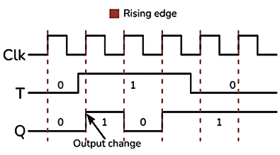
Figure 2. T Flip-Flop Timing Diagram
Now that you understand how the T Flip-Flop works through its truth table, let’s see how to build a T Flip-Flop circuit and make it perform the toggle action in an actual setup.
Making a T Flip-Flop Circuit
You can make a T Flip-Flop by connecting the J and K inputs of a JK Flip-Flop together. This simple setup allows the circuit to toggle its output every time it receives a clock pulse.

Figure 3. Basic T Flip-Flop Circuit Using SR Latch
Some versions of the circuit, like the one using two AND gates and a basic SR latch, may look correct, but they don’t always work properly. The reason is that this design needs a very short clock pulse. If the clock stays high too long, the output Q keeps switching quickly between 1 and 0 during the same pulse. This problem is known as racing. To fix this, you can use an edge-triggered JK Flip-Flop, which responds only to the clock’s rising edge instead of its full pulse.

Figure 4. Edge-Triggered JK Flip-Flop
Another simple way to build a T Flip-Flop is by using a D Flip-Flop with an XOR gate. In this design, the XOR gate makes the input behave like a toggle control, creating a reliable, fully functional edge-triggered T Flip-Flop.

Figure 5. Edge-Triggered T Flip-Flop Using D Flip-Flop and XOR Gate
LED Toggle Using a T Flip-Flop

Figure 6. LED Toggle Circuit Using T Flip-Flop
A T Flip-Flop can be used to make a simple LED toggle circuit that turns an LED on and off with each button press. In this system, the T input is connected to 5V (logic 1), so the flip-flop toggles its output every time it gets a rising edge from the clock input.
A pushbutton is connected to the Clock (Clk) input through a pull-down resistor, which keeps the clock at 0 when the button isn’t pressed. When you press the button, the clock briefly goes from 0 to 1, triggering the flip-flop.
Each time the button is pressed, the output Q changes its state, if it was 0, it becomes 1, and if it was 1, it becomes 0. The LED connected to Q will turn on or off with each press, creating a simple toggle effect.
T Flip-Flop in Digital Clocks and Timers
In digital clocks and timers, a T Flip-Flop is used because it can easily change between two states and divide a signal’s frequency by two. Every time it gets a clock pulse, the output switches, from 0 to 1 or from 1 to 0.
In digital clocks, several T Flip-Flops are connected one after another to make counters. These counters keep track of seconds, minutes, and hours as each flip-flop divides the clock signal in half.
In timers, T Flip-Flops help control time intervals. They can turn signals on or off at fixed times, making them perfect in stopwatches, delay circuits, and alarm systems.
How to Connect a T Flip-Flop in a Breadboard
Building a T Flip-Flop on a breadboard is a simple way to see how it works in real life. You can use either a JK Flip-Flop IC (like the CD4027) or a D Flip-Flop with an XOR gate (like CD4013 and CD4030) to make it. Here’s a step-by-step guide using main components:

Figure 7. T Flip-Flop Breadboard Circuit Using CD4013 and CD4070
Materials Needed
• 1x T Flip-Flop circuit (use CD4013+ CD4030 or CD4027 IC)
• 1x Breadboard
• 1x Pushbutton (PB1)
• 2x 10 kΩ resistors (R1, R2), for pull-up and pull-down
• 1x 330 Ω resistor (R3), for the LED
• 1x LED
• Connecting wires
• 5V DC power supply
Connection Steps
Step 1 - Place the IC in the middle of the breadboard (so the pins are on both sides).
Step 2 - Connect the power:
• VCC pin → +5V
• GND pin → Ground
Step 3 - Set the T input:
• Connect the T input (or J and K shorted together if using JK Flip-Flop) to 5V through a wire. This keeps T = 1 for toggling.
Step 4 - Add the clock button:
• Connect the pushbutton to the Clk pin.
• Use a 10 kΩ pull-down resistor from Clk to ground so the clock stays at 0 when not pressed.
• When pressed, the button sends a short 0→1 pulse to toggle the output.
Step 5 - Connect the output:
• Attach the LED to the Q output pin through the 330 Ω resistor (R3).
• The LED’s other leg goes to ground.
Step 6 - Check wiring and connect the power supply.
Advantages and Disadvantages of T Flip-Flops
T Flip-Flops Advantages:
Easy to Use - Has only one input, so it’s simple to connect and understand.
Toggles Output - Changes state (ON/OFF) with every clock pulse.
Divides Frequency - The output frequency is half of the clock input, useful in clocks and counters.
Stores Data - Can store one bit of information.
Made from Other Flip-Flops - Can be built using JK or D Flip-Flops easily.
T Flip-Flops Disadvantages:
No Set or Reset - You can’t directly set the output to 1 or 0.
Racing Issue - If the clock pulse is too long, the output may change too quickly.
Needs Edge Triggering - Works best when triggered by the clock edge.
Limited Use - Only toggles, so it’s less flexible than other flip-flops.
Small Delay - When used in a series, small delays can affect timing.
T Flip-Flop vs JK Flip-Flop
Here’s a simple comparison between the T Flip-Flop and the JK Flip-Flop to understand how they differ and relate:
|
Feature |
T
Flip-Flop |
JK
Flip-Flop |
|
Full Name |
Toggle Flip-Flop |
JK (Jack-Kilby)
Flip-Flop |
|
Number of Inputs |
1 (T) |
2 (J and K) |
|
Main Function |
Toggles the output on
every clock pulse when T = 1 |
Can set, reset, or
toggle depending on J and K values |
|
Input Relation |
Simplified version of
JK (T = J = K) |
More flexible —
separate control for Set and Reset |
|
Operation |
When T = 0 → output
holds; T = 1 → output toggles |
J = 0, K = 0 → Hold;
J = 1, K = 0 → Set; J = 0, K = 1 → Reset; J = 1, K = 1 → Toggle |
|
Complexity |
Simple |
More complex |
|
Common Use |
Counters, frequency
dividers, LED toggling |
Universal flip-flop
used for all basic flip-flop operations |
|
Racing Problem |
Can occur in
level-triggered circuits |
Also occurs in
level-triggered form but fixed in edge-triggered type |
|
Edge Triggered
Version |
Yes, often made using
D Flip-Flop + XOR |
Yes, standard JK
Flip-Flop can be edge-triggered |
|
Set/Reset Inputs |
Usually not available |
Commonly includes
preset and clear (set/reset) inputs |
Conclusion
The T Flip-Flop is an important part of digital electronics. It toggles its output with each clock pulse and helps in counting and timing tasks. By understanding how it works and how to connect it, you can use it in many simple projects like counters, clocks, and LED control circuits.
function test. The highest cost-effective products and the best service is our eternal commitment.
Hot Article
- LM358 Dual Operational Amplifier Comprehensive Guide: Pinouts, Circuit Diagrams, Equivalents, Useful Examples
- Are CR2032 and CR2016 Interchangeable?
- Understanding the Differences ESP32 and ESP32-S3 Technical and Performance Analysis
- Choosing the Right Battery: A Guide to AG4, LR626, LR66, 177/376/377, SR626, and SR626SW Equivalents
- BC547 Transistor Basics: Pinout, Application Circuits, Alternative/Complementary Models
- NPN vs. PNP: What's the Difference?
- esp32 vs stm32: which microcontroller is better for you?
- What Is a MOSFET and How It Works?
- Electrical Relay Basic: Working Operation, Types and Uses
- PNP Transistors: Structure, Working Principle and Application
 Guide to Sodium Vapor Lamps Operation Circuit and Uses
2025-10-23
 How USB Works and Transfers Data and Power?
2025-10-22
Frequently Asked Questions [FAQ]
1. Why is it called a Toggle Flip-Flop?
It’s called a Toggle Flip-Flop because its output alternates (toggles) between 0 and 1 every time the clock signal is triggered.
2. How is a T Flip-Flop different from a D Flip-Flop?
A D Flip-Flop transfers input to output, while a T Flip-Flop toggles the output only when the T input is high.
3. Can a T Flip-Flop be made using a JK Flip-Flop?
Yes. By connecting the J and K inputs together, a JK Flip-Flop acts as a T Flip-Flop.
4. What is meant by edge-triggered T Flip-Flop?
It means the output changes only during the rising or falling edge of the clock signal, reducing errors like multiple toggles.
5. How does a T Flip-Flop divide frequency?
Every time the clock pulses, the output toggles, so the output frequency becomes half of the clock frequency.
Hot Part Number
 TPS5410MDREP
 08055U5R6BAT2A
 UCC2892PWR
 STM32L071RBT6TR
 CDC337DWR
 VI-JWB-MZ
 TRSF3243CPWR
 KP236N6165XTMA1
 TBJD476K016LSSB0023
 VT261WFQR-ADJ
- CC0603JRX7R8BB224
- GRM1886S1HR90CD01D
- LC75833W-TBM-E
- GRM1556S1H6R5DZ01D
- BDW84C
- 06035U5R6CAT2A
- BQ40Z80RSMT
- AM5728BABCXEA
- T491C475K025AT2478
- RGTVX6TS65DGC11
- TPS2044BD
- 12065C105JAT2A
- T491D336K025ATAUTO7280
- TS5A22364DGSR
- CGA2B2X8R1H152M050BE
- VE-220-IY
- X1205S8I
- CX0805MRX7R8BB223
- 08055U101KAT4A
- MCC40-10I08
- ADT7421ARMZ
- AK4340ET
- ATD97SC3202-X1AC
- CS5532ASZ
- CY14E256LA-SZ25X
- HD155141
- LM4880MX
- M60089H-0201Y
- MB89615-150
- S-93C56BD0I-T8T1GE
- MIP2K40MSSCF
- IC41C16100S-50K
- LV1605ML-MPB-E
- PSN76025A0
- VT1622AG
- ANA37326B
- AND0241RM27Q7
- CXD2913AQ
- CY7C1382D-200BZXC