Potentiometers vs Encoders Working, Types, Features, and Uses
2026-01-12
2445
Catalog
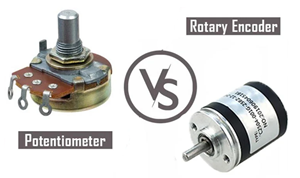
Figure 1. Potentiometers vs Rotary Encoders
What Are Rotary Input Devices?
Rotary input devices are electronic parts that let you control something by turning a knob. When the knob is rotated, the device changes that movement into an electrical signal that a circuit or controller can understand. These devices are used to adjust things like volume, speed, brightness, or position. You can find them in radios, speakers, machines, home appliances, and DIY electronics projects.
There are two common types of rotary input devices: potentiometers and rotary encoders. Potentiometers change the signal smoothly as you turn the knob, which makes them suitable for simple and direct control. Rotary encoders, on the other side, send digital signals and are better for accurate control and endless rotation. Let’s take a closer look at how these two rotary input devices work and where each one is best used.
Understanding Potentiometers
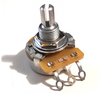
Figure 2. Potentiometers
A potentiometer is a simple electronic part that lets you control a value by turning a knob or dial. Inside the potentiometer is a resistive path and a small moving contact called a wiper. When the knob is turned, the wiper moves along the resistive path, changing the resistance and adjusting the output voltage.
The voltage changes smoothly as the knob turns, which allows gradual and easy control. Result of this, potentiometers are applied for volume controls, light dimmers, motor speed controllers, tuning knobs, and simple position sensing. They are easy to connect, simple to use, and do not require any software or programming.
Potentiometers are popular because they are low cost and provide an immediate position signal, even when power is turned off. However, since they rely on physical contact, the parts can wear out over time and may be affected by dust, vibration, and electrical noise.
How Potentiometers Works
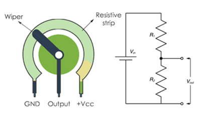
Figure 3. Potentiometer Working Principle
A potentiometer works by dividing voltage inside a circuit. It has three pins: two outer pins connected to a resistive path and a middle pin connected to a moving part called the wiper. A fixed voltage is applied to the two outer pins.
When you turn the knob, the wiper moves along the resistive path. This movement changes the resistance on each side of the wiper. Because of this, the voltage taken from the middle pin changes.
If the wiper moves closer to the power side, the output voltage becomes higher. If it moves closer to the ground side, the voltage becomes lower. This allows the potentiometer to change voltage smoothly as the knob is turned.
This simple working method makes potentiometers perfect for controls that need smooth adjustment, such as volume, brightness, and speed control.
Types of Potentiometers
Potentiometers come in different types, and each type is designed for a specific way of control or application.
Rotary potentiometers are the standard type of potentiometer. They are adjusted by turning a knob in a circular motion and are frequently found in volume controls, tuning knobs, and adjustment dials.
Linear potentiometers operate by sliding a knob or lever in a straight line. Linear potentiometers are found in audio mixers, control panels, and equipment where straight movement is more practical.
Trimmer potentiometers are small adjustable parts designed for fine tuning. They are usually adjusted with a screwdriver and are placed on circuit boards for calibration.
Digital potentiometers are electronic versions that are controlled by digital signals instead of manual movement. They are typically applied in modern systems with microcontrollers where accurate and repeatable control is required.
Each type of potentiometer is chosen based on how it is adjusted, the level of accuracy required, and the application where it is applied.
Understanding Rotary Encoders
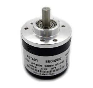
Figure 4. Rotary Encoders
A rotary encoder is a device that reads rotational movement and converts it into digital signals. When the shaft or knob is turned, the encoder generates electrical pulses that represent movement.
These pulses tell a control system how much the shaft has turned and which direction it moved. Some encoders can also indicate rotation speed. Unlike potentiometers, rotary encoders can rotate continuously without stopping at fixed positions.
Because they send digital signals and do not rely on changing resistance, rotary encoders are well suited for accurate control and long-term use in electronic systems.
How Rotary Encoders Works
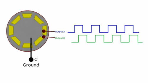
Figure 5. Rotary Encoder Working Principle
Rotary encoder works by detecting rotation and turning that movement into digital signals. When you rotate the shaft or knob, the encoder does not change resistance. Instead, it creates a series of electrical pulses.
Inside the encoder are sensing parts that react as the shaft turns. Every small movement produces pulses. These pulses are sent to a controller, which counts them to know how far the knob has turned. By checking the order of the signals, the controller can also tell which direction the knob is rotating.
Some rotary encoders can also help measure speed, based on how fast the pulses are generated. As the encoder sends digital signals, it can rotate endlessly without a fixed start or end point.
Types of Rotary Encoders
Rotary encoders come in different types, and each type works best for certain applications.
Incremental rotary encoders generate a series of pulses as the shaft turns. These pulses are counted to know how much rotation has happened and in which direction. They are simple in design and are found where relative movement tracking is enough.
Absolute rotary encoders provide a unique position value for each shaft position. This means the system always knows the exact position, even after power is turned off. They are suitable for systems that need reliable position information at all times.
Based on sensing method, encoders can also be grouped as optical encoders and magnetic encoders. Optical encoders use light and sensors to detect movement, offering high accuracy. Magnetic encoders use magnetic fields, making them more resistant to dust, vibration, and harsh environments.
Potentiometers vs Rotary Encoders Features
|
Feature |
Potentiometers |
Rotary
Encoders |
|
Output type |
Analog voltage output |
Digital pulse output |
|
Working method |
Changes resistance as
the knob turns |
Generates pulses as
the shaft rotates |
|
Rotation range |
Limited rotation (has
start and end) |
Continuous rotation
(no limit) |
|
Position feedback |
Direct position based
on knob location |
Position calculated
by counting pulses |
|
Accuracy |
Good for basic
control |
Better for precise
and repeatable control |
|
Durability |
Uses physical
contact, can wear out |
Less physical
contact, longer lifespan |
|
Sensitivity |
Affected by dust,
vibration, and noise |
More resistant,
especially magnetic types |
|
Circuit complexity |
Very simple to
connect |
Needs signal reading
and processing |
|
Programming needed |
Not required |
Often required |
|
Cost |
Low cost |
Higher cost than
potentiometers |
|
Best suited for |
Simple, manual
controls |
Digital systems and
precise control tasks |
Potentiometers vs Rotary Encoders Applications
Potentiometers and rotary encoders are used in different applications, as shown below.
|
Application |
Potentiometers |
Rotary
Encoders |
|
Audio control |
Volume knobs, tone
controls |
Digital volume knobs,
audio menus |
|
Lighting control |
Light dimmers,
brightness adjustment |
Lighting systems with
digital control |
|
Motor control |
Simple motor speed
adjustment |
Motor position,
speed, and direction feedback |
|
User input devices |
Manual adjustment
knobs |
Menu navigation
knobs, jog wheels |
|
Position sensing |
Basic position
feedback |
Precise and
repeatable position tracking |
|
Industrial equipment |
Simple control panels |
CNC machines,
robotics, automation systems |
|
Consumer electronics |
Radios, speakers,
small appliances |
Washing machines,
smart appliances |
|
DIY & learning
projects |
Beginner electronics
projects |
Advanced
microcontroller projects |
|
Reliability needs |
Short-term or
low-stress use |
Long-term and
heavy-use systems |
Choosing Between Encoder and Potentiometer
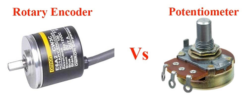
Figure 6. Potentiometers vs Rotary Encoders
If you need simple, smooth, and low-cost control, such as adjusting volume or brightness, a potentiometer is usually the better choice. It is easy to connect, does not need programming, and gives direct position feedback.
If your project needs higher accuracy, digital control, or continuous rotation, a rotary encoder is more suitable. Encoders work well with microcontrollers, last longer in heavy-use systems, and are ideal for menus, motors, and automation tasks.
Conclusion
Potentiometers and rotary encoders are both useful control devices in electronics. Potentiometers are simple, low in cost, and good for smooth manual control. Rotary encoders are better for digital systems that need accuracy and long life. By understanding their differences and uses, you can choose the right device for your project with confidence.
function test. The highest cost-effective products and the best service is our eternal commitment.
Hot Article
- LM358 Dual Operational Amplifier Comprehensive Guide: Pinouts, Circuit Diagrams, Equivalents, Useful Examples
- Are CR2032 and CR2016 Interchangeable?
- Understanding the Differences ESP32 and ESP32-S3 Technical and Performance Analysis
- BC547 Transistor Basics: Pinout, Application Circuits, Alternative/Complementary Models
- Choosing the Right Battery: A Guide to AG4, LR626, LR66, 177/376/377, SR626, and SR626SW Equivalents
- NPN vs. PNP: What's the Difference?
- esp32 vs stm32: which microcontroller is better for you?
- What Is a MOSFET and How It Works?
- Electrical Relay Basic: Working Operation, Types and Uses
- PNP Transistors: Structure, Working Principle and Application
 A Practical Guide to IPC-A-610 for PCB Assembly and Quality Control
2026-01-12
 D Flip-Flop Symbol, Working, Truth Table, Applications, and Types
2026-01-12
Frequently Asked Questions [FAQ]
1. What is the main difference between a potentiometer and a rotary encoder?
A potentiometer outputs a changing analog voltage, while a rotary encoder sends digital pulses that represent movement and direction.
2. Can a rotary encoder replace a potentiometer?
Yes, in digital systems that use microcontrollers, but not in simple analog circuits without signal processing.
3. Do rotary encoders wear out like potentiometers?
Most rotary encoders last longer because they have less physical contact than potentiometers.
4. Why do potentiometers have only three pins?
Two pins connect to the resistive path, and the middle pin provides the adjustable output voltage.
5. What does “continuous rotation” mean in rotary encoders?
It means the shaft can turn endlessly without a fixed start or end position.
6. Can potentiometers be used for position sensing?
Yes, but only for basic position sensing within a limited rotation range.
Hot Part Number
 CGA9N3X7S2A106K230KB
 C3216X7S0G476M160AB
 CL05B562KA5NNNC
 CGA3E3X8R2A333M080AD
 1206PC473KAT2A
- CL10C151GB8NNWC
 GCM1555C1H391JA16D
 GRM1885C2A8R0DA01J
 GQM2195C1H470GB01D
 GRM0336R1E1R2CD01D
- T510E108M004AS4115
- BZT52C5V1T-7
- 843252AGLFT
- RTC-72421B
- LAN9514-JZX-TR
- XRT86VX38IB256-F
- VI-JT3-EW
- EP1S25F1020C5
- S912B32E4VFUE8R
- V48C12C150B
- V300A48M500BL
- 6MBI35S-140-50
- NCV2903DMR2G
- CAT3200ZI-GT3
- ADG721BRMZ-REEL
- T491D106M035AT7128
- F6KA2G605A4LA-Z
- AD9226ARSZRL
- ADS8341EB
- LC898212XD-SH
- TPS2541RTET
- LP2953IM-3.3
- ADF4106BRUZRL
- ATAR862N-087-TNQ38
- BCM5751MKFBG
- BQ20881DBTR
- EL2120CS
- K4B4G1646E-BCK0
- M5M5V108DKV-70HI
- MC14051BCP
- MPC993FA
- PI3HDMI2410-AFFE
- XCS20XL5TQ144C
- APA2621RI-TRG
- DS24B33S+T&R
- IDT71V321L25TFI
- RTL8366S-VS-GR
- SKKT215/16E
- EXO-3C16MHz