NOR Gates: Operation, Types, and Uses
2025-12-12
3764
Catalog
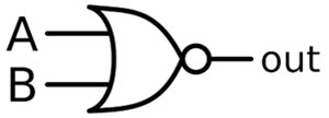
What Is a NOR Gate?
A NOR gate outputs HIGH only when every input is LOW. If even one input goes HIGH, the output drops to LOW.
For a two input NOR gate:

It behaves exactly like an OR gate whose output is inverted.
How NOR Gates Work Inside and Out?
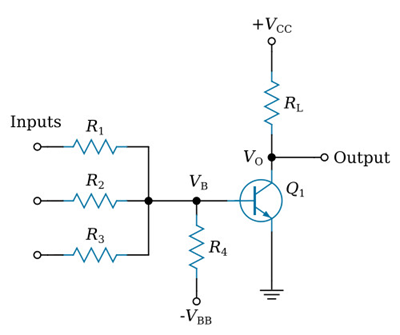
Figure 2. Transistor-Based NOR Gate
NOR gates can be understood both from their transistor structure and their logic operation. In a basic RTL design, each input drives a transistor. When an input is HIGH, that transistor switches on and pulls the output LOW, and when all inputs are LOW, none of the transistors conduct, allowing a pull-up resistor to set the output HIGH. This hardware behavior matches the logic view of a NOR gate, which works like an OR stage followed by a NOT stage. The OR part checks whether any input is HIGH, and the small circle on the symbol shows the inversion that produces the final LOW or HIGH output. Like OR gates, NOR gates can have two or more inputs but always provide a single output.
NOR Gate Truth Table
(For a two input gate)
|
A |
B |
Q |
|
0 |
0 |
1 |
|
0 |
1 |
0 |
|
1 |
0 |
0 |
|
1 |
1 |
0 |
Different NOR Gate Types
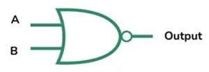
Figure 3. 2-Input NOR Gate
2 Input NOR Gate: This is the simplest NOR gate. It uses two inputs and one output with four possible input combinations. The output is HIGH only when both inputs are LOW.
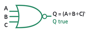
Figure 4. 3-Input NOR Gate
3 Input NOR Gate: A 3 input NOR gate extends the same rule to three inputs. The output is HIGH only when all three inputs are LOW. This helps reduce gate count in circuits that need multiple conditions evaluated at once.

Figure 5. Multi-Input NOR Gate
Multi Input NOR Gate: A multi input NOR gate handles any number of inputs. If all inputs are LOW, the output is HIGH. If any input is HIGH, the output is LOW. This is useful in systems where many signals need to be inactive before an action can occur.
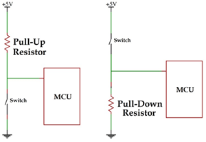
Figure 6. Using Pull-Up and Pull-Down Resistors
Handling Unused Inputs: Unused inputs should never be left floating. Tie them to ground using a pull down resistor to keep outputs stable.
CMOS and TTL NOR ICs
|
IC
Model |
Logic
Family |
Number
of Gates |
Inputs
per Gate |
Supply
Voltage Range |
Typical
Propagation Delay |
Output
Drive |
Package
Options |
|
CD4001 |
CMOS |
4 gates |
2-input |
3V to 15V |
50–200 ns (varies with VDD) |
Moderate |
DIP, SOIC, TSSOP |
|
CD4025 |
CMOS |
3 gates |
3-input |
3V to 15V |
70–250 ns |
Moderate |
DIP, SOIC, TSSOP |
|
74HC02 |
High-speed CMOS (HC) |
4 gates |
2-input |
2V to 6V |
8–15 ns |
Strong |
DIP, SOIC, TSSOP |
|
74HC27 |
High-speed CMOS (HC) |
3 gates |
3-input |
2V to 6V |
10–18 ns |
Strong |
DIP, SOIC, TSSOP |
NOR Gate Uses
Inverter- Tie one input to ground and the gate acts as a NOT gate.
General logic functions- Because NOR is universal, any Boolean function can be built from NOR combinations.
Decoders- They can detect when an entire set of monitored bits is LOW.
Arithmetic and control logic- Used for gating, decision making, and carry related operations.
Programmable logic- Many PAL and PLA structures map functions using NOR based arrays.
NOR Gates in Memory Circuits
1. SR Latch Using NOR Gates: NOR gates can be used to build simple memory circuits, with the SR latch being the most direct example. Two NOR gates are connected in a feedback loop so the output can hold its value. The S input sets the output HIGH, the R input resets it LOW, and when both inputs are LOW, the latch keeps its previous state. This feedback action allows the circuit to store a single bit of information.
2. Gated Latches: Gated latches build on the SR latch by adding an enable control, ensuring the stored value changes only when permitted. This improves stability and prevents unwanted updates.
3. D Latches: A D latch simplifies storage control by generating valid S and R signals from a single D input. When the enable signal is HIGH, the latch follows the D input; when the enable is LOW, the latch holds its last stored value.
4. Flip-Flops: Flip-flops combine two latches to capture data precisely on a clock edge. They are importantin digital circuits such as counters, registers, and timing systems.
Pros and Cons of NOR Gates
Pros
• Universal for all logic functions
• Predictable and simple
• Low power in CMOS
• Easy to troubleshoot
• Good noise tolerance
• Inexpensive and widely available
Cons
• Not always efficient for complex logic
• Can require many gates for certain functions
• Speed drops with high input counts
• Not ideal for very high speed arithmetic
Conclusion
NOR gates may be small, but they power many of the logic and memory functions used in modern electronics. Their simple rules make them easy to learn while still offering a lot of flexibility. Knowing how they work gives you a strong base for understanding digital circuits.
function test. The highest cost-effective products and the best service is our eternal commitment.
Hot Article
- LM358 Dual Operational Amplifier Comprehensive Guide: Pinouts, Circuit Diagrams, Equivalents, Useful Examples
- Are CR2032 and CR2016 Interchangeable?
- Understanding the Differences ESP32 and ESP32-S3 Technical and Performance Analysis
- Choosing the Right Battery: A Guide to AG4, LR626, LR66, 177/376/377, SR626, and SR626SW Equivalents
- BC547 Transistor Basics: Pinout, Application Circuits, Alternative/Complementary Models
- NPN vs. PNP: What's the Difference?
- esp32 vs stm32: which microcontroller is better for you?
- What Is a MOSFET and How It Works?
- Electrical Relay Basic: Working Operation, Types and Uses
- PNP Transistors: Structure, Working Principle and Application
 What Is an XOR Gate? A Simple Guide
2025-12-15
 What Is Light Dependent Resistors (LDR)? A Simple Guide
2025-12-12
Frequently Asked Questions [FAQ]
1. Can NOR gates be used to build a full adder?
Yes. Since NOR is universal, you can design a full adder entirely from NOR gates, though it may require many stages.
2. Is a NOR gate faster than an OR gate?
In most technologies, NOR is slightly slower than OR due to the added inversion, but the difference is small in modern ICs.
3. Why is the NOR gate considered a universal gate?
Because you can build every other logic gate and any digital circuit using only NOR combinations.
4. How does a NOR gate behave with more than two inputs?
The output stays HIGH only when every input is LOW. One HIGH input forces the output LOW.
5. Can a NOR gate replace a NOT gate?
Yes. Tie all but one input to LOW, and the NOR function acts as an inverter.
6. What happens if a NOR gate input is left floating?
Floating inputs cause unstable output levels. Always tie unused inputs to ground.
7. Are NOR gates used in modern processors?
Yes. NOR structures appear in control logic, memory cells, and optimized logic blocks inside CPUs.
8. Do NOR gates consume more power than NAND gates?
NOR gates usually use more transistors than NAND gates in CMOS, so they tend to consume slightly more power.
9. How do you test a NOR gate on a breadboard?
Apply known HIGH and LOW signals to the inputs and verify the output stays HIGH only when all inputs are LOW.
Hot Part Number
 CX0805MRX7R8BB223
 CGA2B2X8R1H152M050BE
 08055U101KAT4A
 CC0603JRX7R8BB224
- 08055U5R6BAT2A
 06035U5R6CAT2A
 12065C105JAT2A
 GRM1886S1HR90CD01D
 TBJD476K016LSSB0023
 BDW84C
- X1205S8I
- VE-220-IY
- VI-JWB-MZ
- KP236N6165XTMA1
- MCC40-10I08
- T491D336K025ATAUTO7280
- TRSF3243CPWR
- AM5728BABCXEA
- LC75833W-TBM-E
- UCC2892PWR
- CDC337DWR
- T491C475K025AT2478
- TPS2044BD
- STM32L071RBT6TR
- TPS5410MDREP
- TS5A22364DGSR
- ADT7421ARMZ
- AK4340ET
- ATD97SC3202-X1AC
- CS5532ASZ
- CY14E256LA-SZ25X
- HD155141
- LM4880MX
- M60089H-0201Y
- MB89615-150
- S-93C56BD0I-T8T1GE
- VT261WFQR-ADJ
- MIP2K40MSSCF
- IC41C16100S-50K
- LV1605ML-MPB-E
- PSN76025A0
- BQ40Z80RSMT
- VT1622AG
- ANA37326B
- AND0241RM27Q7
- CXD2913AQ
- CY7C1382D-200BZXC
- GD25Q64CFIG
- RGTVX6TS65DGC11