Learn Half-Wave Rectifier: Working, Symbol, Circuit, Applications and Output
2025-12-18
5160
Catalog

Figure 1. Half-Wave Rectifier Circuit
What is a Half-Wave Rectifier?
Half-wave rectifier is the simplest type of rectifier used to convert alternating current (AC) into direct current (DC). Half-wave rectifier works by allowing only one half of the AC waveform to pass through while blocking the other half. This is done using a single diode, along with a load resistor, and sometimes a transformer for isolation or voltage adjustment.
The output produced by a half-wave rectifier flows in only one direction, but it is not smooth. Instead, it appears as a series of pulses, known as pulsating DC. Because of this, a filter is usually added to make the output more stable. Since half of the AC waveform is not used, the efficiency of a half-wave rectifier is lower than that of a full-wave rectifier.
Half-Wave Rectifier Symbol
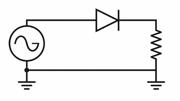
Figure 2. Half-Wave Rectifier Symbol
The half-wave rectifier includes an AC source, a diode, and a load resistor. The diode allows current to flow in only one direction, so only one half of the AC waveform passes through while the other half is blocked. The output voltage appears across the resistor and flows in a single direction, creating pulsating DC. This symbol represents the most basic form of rectification and is used to explain how AC power is converted into DC.
Half-Wave Rectifier Circuit Diagram

Figure 3. Half-Wave Rectifier Circuit Diagram
The AC supply is first connected to a step-down transformer, which reduces the voltage and provides isolation. The AC output from the transformer is then applied to a single diode. During one half of the AC cycle, the diode allows current to flow through the load resistor, producing output voltage. During the other half, the diode blocks the current. As a result, the voltage across the load is pulsating DC, which flows in only one direction.
Output Waveform of Half-Wave Rectifier
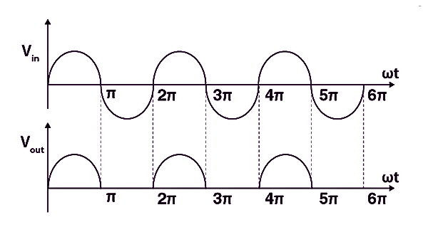
Figure 4. Output Waveform of a Half-Wave Rectifier
The top wave is the input AC voltage, which has both positive and negative cycles. The bottom wave is the output voltage, where only the positive half of the AC signal appears. During the positive half-cycle, the diode conducts and voltage is present at the output. During the negative half-cycle, the diode blocks the current, so the output voltage becomes zero. This results in a pulsating DC output that flows in one direction but is not smooth.
Half-Wave Rectifier Calculation Formulas
Peak Input Voltage:
Vm
=
maximum value of the AC input voltage
Average (DC) Output Voltage:
π
Average (DC) Output Current:
π
RMS Output Voltage:
2
RMS Output Current:
2
Ripple Factor:
Rectification Efficiency:
Peak Inverse Voltage (PIV) of Diode:
Power Losses in Half-Wave Rectifier
Why does a half-wave rectifier waste energy? This circuit uses only one portion of the incoming AC signal, while the remaining portion is blocked by the diode and produces no output. Extra energy is dissipated as heat in the diode, connecting wires, and load resistor. These losses greatly reduce the usable output, which limits this rectifier to educational use, lab demonstrations, and basic test circuits, rather than power-demanding applications.
Efficiency of Half-Wave Rectifier
The efficiency of a half-wave rectifier indicates how effectively it changes input AC power into DC output power. Under ideal conditions, its highest possible efficiency is about 40.6%, meaning less than half of the supplied energy becomes useful output. In practical circuits, this value drops further due to internal resistance and component losses, making the rectifier unsuitable for efficient power conversion.
Ripple Factor in Half-Wave Rectifier
Ripple factor describes the amount of variation remaining in the rectified output voltage. Because the half-wave rectifier produces DC in separated pulses, the output contains efficient fluctuations instead of a steady level. Without any smoothing components, the ripple factor is approximately 1.21, showing that the fluctuating portion is greater than the average output. To reduce this effect, a filter capacitor is added to smooth the voltage.
Half-Wave Rectifier with Filter Capacitor
Half-wave rectifier with a filter capacitor helps make the output voltage less bumpy and more steady. The capacitor is placed across the load resistor. When the diode allows current to pass, the capacitor stores energy by charging up. When the diode turns off, the capacitor releases this stored energy to the load. This fills in the gaps between pulses and reduces ripple in the output. While this improves the DC output, it is still not as smooth or efficient as other rectifier types.
Advantages & Disadvantages of Half-Wave Rectifier
Advantages of a Half-Wave Rectifier:
• Very simple circuit design
• Requires only one diode
• Small circuit size
• Useful for low-current applications
Disadvantages of a Half-Wave Rectifier:
• Very low efficiency
• Uses only half of the AC input cycle
• Output voltage contains large ripple
• DC output is not smooth
• Poor voltage regulation
• Not suitable for high-current or high-power use
• Higher power loss compared to other rectifiers
• Requires large filter components to improve output
Half-Wave Rectifier vs Full-Wave Rectifier
Half-wave rectifier converts AC to DC using only one half of the AC waveform, making it simple but inefficient. A full-wave rectifier uses both halves of the AC waveform, producing smoother and more efficient DC output.
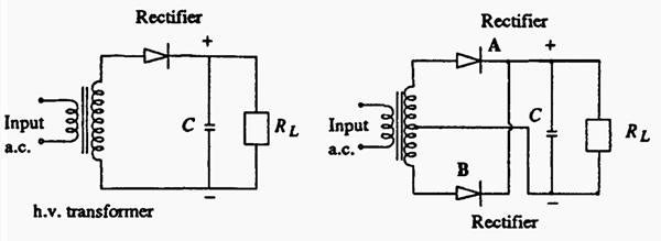
Figure 5. Half-Wave Rectifier vs Full-Wave Rectifier
Applications of Half-Wave Rectifiers
Educational – used to teach basic rectifier and diode concepts
Laboratory – applied in simple test and demonstration circuits
Student projects – used in basic electronics builds
AM radio detection – helps detect audio signals from radio waves
Low-power battery charging – suitable for small, low-current devices
Simple power supplies – provides basic DC output where smoothness is not required
Prototype circuits – used for quick testing due to simple design
Signal clipping circuits – limits part of a signal waveform
LED indicator circuits – powers LEDs in low-current applications
Timing and triggering circuits – provides basic DC pulses
Sensor power sources – supplies DC to simple sensors
DIY electronics kits – commonly included in beginner kits
Rectifier demonstrations – used to show AC-to-DC conversion visually
Conclusion
The half-wave rectifier is a simple and low-cost way to convert AC into DC, mainly used for learning and basic experiments. Although it has low efficiency and high ripple, it helps you understand the basic idea of rectification and prepares you for more advanced rectifier circuits.
function test. The highest cost-effective products and the best service is our eternal commitment.
Hot Article
- LM358 Dual Operational Amplifier Comprehensive Guide: Pinouts, Circuit Diagrams, Equivalents, Useful Examples
- Are CR2032 and CR2016 Interchangeable?
- Understanding the Differences ESP32 and ESP32-S3 Technical and Performance Analysis
- Choosing the Right Battery: A Guide to AG4, LR626, LR66, 177/376/377, SR626, and SR626SW Equivalents
- BC547 Transistor Basics: Pinout, Application Circuits, Alternative/Complementary Models
- NPN vs. PNP: What's the Difference?
- esp32 vs stm32: which microcontroller is better for you?
- What Is a MOSFET and How It Works?
- Electrical Relay Basic: Working Operation, Types and Uses
- PNP Transistors: Structure, Working Principle and Application
 DPST Switch Basics: Wiring, Terminals, and Applications
2025-12-18
 Learn More About Clipper Circuits
2025-12-17
Frequently Asked Questions [FAQ]
1. What happens if the diode is connected the wrong way in a half-wave rectifier?
If the diode is reversed, the output will appear during the opposite half of the AC cycle, but rectification will still occur.
2. Can a half-wave rectifier work without a transformer?
Yes, it can work directly from an AC source, but a transformer is recommended for voltage control and safety.
3. What type of diode is best for a half-wave rectifier?
A standard silicon diode is commonly used, while fast or Schottky diodes are chosen for low-voltage or high-speed needs.
4. Can a half-wave rectifier produce negative DC output?
Yes, if the diode orientation is reversed, the output pulses will be negative instead of positive.
5. What happens if no load resistor is connected?
Without a load, no useful output current flows, and voltage measurement becomes unstable.
6. Is half-wave rectification used in signal processing?
Yes, it is sometimes used for signal detection and envelope detection.
Hot Part Number
 C1608X7R1E474K080AB
 C2012X5R0J225K085AA
 GRM0225C1E4R1CDAEL
 CC0603ZRY5V6BB474
 UMK316B7474ML-T
 08051U150GAT2A
 GRM1886S1H1R1CZ01D
 T495D476K010ATE080
 TPSE106M050R0500
 APA600-PQ208
- MT47H64M8CF-25E:G
- MC9S12XA512VAL
- IS42S16160B-6TL
- SI8233AD-D-IS
- RT0402DRD072K49L
- CY8C20140-SX2I
- VLF4012AT-100MR79
- SKM150GAL128D
- MC100ELT21DR2G
- MC14040BDTR2G
- LT3971AIMSE#PBF
- T491D107K006ZT7280
- UCC3818N
- INA240A2PW
- IXFP22N65X2M
- LT1999CMS8-50F#PBF
- SN74LVC32ADR
- AD5262BRUZ20-RL7
- ATMXT1666T2-C2U
- BU20360-48L
- ICS950218AFT
- MAX1779EUE+TG104
- MAX202ECWE-T
- MAX8860EUA27
- G5LA-1A4-12V
- HN29V256AOBBP-30
- M66445M1FA
- NFP-2200-A3
- PCD8010H/E31/4
- PEAD22653AFV1QH14NAR
- 6MBP150RTM060
- S29GL032A90FAIR43
- TMR3-1211
- T6TD7XBG-0001
- CS242C001PZ-TRSV
- IBMPPCBWY-GES72914
- SDINBDG4-8G-XI1
- XFL4020-332MEC
- GMOV-14D500K