How to Wire a 4-Pin & 5-Pin Relay
2026-04-27
938
Catalog
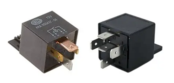
Figure 1. 4-Pin vs 5-Pin Relay Example
What Is a 4-Pin and 5-Pin Relay?
A 4-pin relay and a 5-pin relay are both electrical switches that use a small signal to control a larger circuit. They work the same way internally, using a coil and a moving contact, but the difference is in how many connections they provide and how the output behaves.
A 4-pin relay has four terminals: two are for the coil (usually pins 85 and 86), one is the common input (pin 30), and one is the output (pin 87). This type uses a normally open (NO) connection, which means the circuit is OFF by default. When the relay is activated, pin 30 connects to pin 87, allowing current to flow and turning the device ON.
A 5-pin relay has one extra terminal called pin 87a. This adds a normally closed (NC) connection. When the relay is OFF, pin 30 is connected to 87a. When the relay is activated, the connection switches from 87a to 87. This allows you to choose whether your device starts in an ON or OFF state.
Relay Pinout Configuration
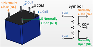
Figure 2. Relay Pinout and Symbol Diagram
Pins 85 and 86 (Coil) - These pins control the relay. You connect one to power and the other to ground. When voltage is applied, the relay is activated.
Pin 30 (Common) - This is the main input connection. It carries the power that will be switched to another pin.
Pin 87 (Normally Open - NO) - This pin is not connected to pin 30 when the relay is off. When the relay turns on, pin 30 connects to pin 87, allowing current to flow.
Pin 87a (Normally Closed - NC) - This pin is only found in 5-pin relays. It is connected to pin 30 when the relay is off. When the relay turns on, this connection is disconnected.
4-Pin vs 5-Pin Relay: Key Differences
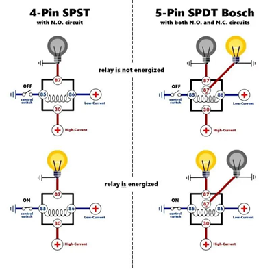
Figure 3. 4-Pin vs 5-Pin Relay Operation Diagram
The difference between a 4-pin and a 5-pin relay is the number of switching options they provide. Both types use pins 85 and 86 for the coil and pin 30 as the common connection. The difference is in how the output is handled.
A 4-pin relay has only one output, which is pin 87. This is a normally open (NO) connection, meaning the circuit is off by default. When the relay is activated, pin 30 connects to pin 87, and the device turns on. This type is simple and is commonly used when you only need to turn something on when power is applied.
A 5-pin relay adds an extra pin, 87a. This is a normally closed (NC) connection. When the relay is off, pin 30 is connected to 87a. When the relay is activated, the connection switches from 87a to 87. This gives you more control because you can choose between a default ON or default OFF behavior.
4-Pin vs 5-Pin Relay Comparison Table
|
Feature |
4-Pin
Relay |
5-Pin
Relay |
|
Number of Pins |
4 |
5 |
|
Coil Pins |
85, 86 |
85, 86 |
|
Common Pin |
30 |
30 |
|
Output Pins |
87 only |
87 and 87a |
|
Normally Open (NO) |
Yes (Pin 87) |
Yes (Pin 87) |
|
Normally Closed (NC) |
No |
Yes (Pin 87a) |
|
Default State (Relay
OFF) |
Circuit is open (OFF) |
Connected to 87a (ON
by default) |
|
When Relay is ON |
30 connects to 87 |
30 switches from 87a
to 87 |
|
Switching Options |
Single path |
Two paths (NO and NC) |
|
Complexity |
Simple |
More flexible |
|
Common Applications |
Basic ON/OFF control |
Circuits needing
default ON or OFF control |
How a Relay Works in Switching Circuits
A relay works as a switch that is controlled by electricity instead of your hand. When a small voltage is applied to the relay’s coil (usually through pins 85 and 86), current flows through the coil and creates a magnetic field. This magnetic force pulls a metal contact inside the relay.
When the contact moves, it changes the path of the circuit. The common pin (30) connects to another pin depending on the relay type. In a 4-pin relay, it connects to pin 87 when activated. In a 5-pin relay, it switches from pin 87a (normally closed) to pin 87 (normally open).
This switching action allows a low-power signal to control a higher-power device. For example, a small control circuit can turn on a fan, light, or motor without directly carrying the high current. When the control voltage is removed, the magnetic field disappears. A spring inside the relay pushes the contact back to its original position, and the circuit returns to its default state. This simple process allows the relay to switch circuits on and off safely and repeatedly.
4-Pin Relay Wiring Diagram
To wire a 4-pin relay, you just need to connect the control side and the load side correctly. Once you follow the right pin connections, the relay will switch your device on when triggered.
First, connect pin 85 and pin 86 to the control circuit. One pin goes to power, and the other goes to ground. You can place a switch on this side so you can control when the relay activates.
Next, connect pin 30 to your main power source. This is the input power that will be sent to your device when the relay turns on. It is a good idea to place a fuse between the power source and pin 30 for protection.
Then, connect pin 87 to your load, such as a light, fan, or motor. This is the output that will receive power when the relay is activated. Finally, connect the other side of your load to ground. This completes the circuit.
When you turn on the control switch, the relay activates. Pin 30 connects to pin 87, and current flows to your device, turning it on. When you turn it off, the connection is broken, and the device turns off.
5-Pin Relay Wiring Diagram
To wire a 5-pin relay, you follow a setup similar to a 4-pin relay, but with one extra connection that gives you more control.
Start by connecting pin 85 and pin 86 to the control side. One goes to power, and the other goes to ground. You can add a switch here to control when the relay turns on. Next, connect pin 30 to your main power source. This is the input power that will be switched to the output.
Then, decide how you want your device to behave:
• If you want the device OFF by default, connect your load to pin 87 (normally open). The device will only turn on when the relay is activated.
• If you want the device ON by default, connect your load to pin 87a (normally closed). The device will turn off when the relay is activated.
Lastly, connect the other side of your load to ground to complete the circuit.
Practical Wiring Examples
Relays are used in real circuits to control devices safely and efficiently. These examples show how the connections work in actual setups.
One example is controlling a car headlight using a relay. The switch sends a small signal to the relay, while the relay connects the battery directly to the headlights. This reduces load on the switch and improves performance.
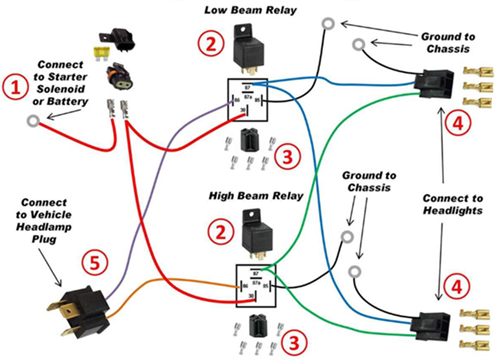
Figure 5. Dual Headlight Relay Wiring Diagram
Another example is using a relay for a cooling fan. A temperature switch activates the relay when the system gets hot. The relay then powers the fan automatically, and turns it off when the temperature goes down.
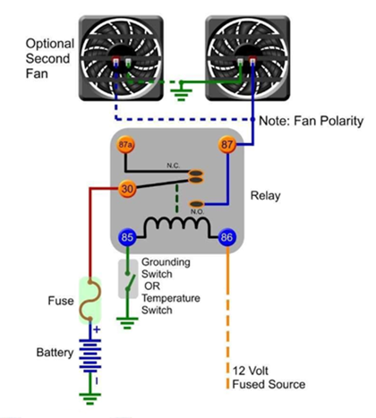
Figure 6. Simple Cooling Fan Relay Wiring Example
You can also use a relay in a microcontroller project, such as with Arduino. The microcontroller sends a low-power signal to the relay module, and the relay switches a higher-power device like a lamp or motor.
Common Relay Wiring Mistakes
Connecting the wrong pins - If you mix up the pins, the relay won’t work. Double-check the pin numbers before you connect anything.
Skipping the fuse - If you don’t add a fuse, a short circuit can damage your wiring. Always place a fuse on the power line going to pin 30.
Using the wrong voltage - If your relay is rated for 12V and you use a different voltage, it may fail. Make sure your power matches the relay rating.
Bad ground connection - If the ground is weak or missing, the relay won’t activate. Make sure your ground connection is clean and secure.
Loose wiring - Loose wires can cause the relay to turn on and off randomly. Secure all connections properly.
Overloading the relay - If you connect a device that draws too much current, the relay can overheat. Check the relay’s current rating first.
Using 87a without knowing it - Pin 87a is active when the relay is off. If you use it by mistake, your device may stay on when you don’t expect it.
Using a Relay with a Microcontroller
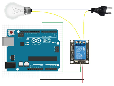
Figure 4. Arduino Relay Control Circuit Example
When you are working with a microcontroller, you cannot directly connect high-power devices like lamps, fans, or motors to its output pins. The microcontroller only provides a small amount of voltage and current, which is not enough to drive these devices safely. This is why a relay is used as a bridge between the low-power control side and the high-power load.
In a common setup, the microcontroller sends a small signal to a relay module. Inside the module, a transistor helps switch the relay on, and a diode protects the circuit from voltage spikes when the relay turns off. Once the relay is activated, it connects the main power source to the device, allowing it to turn on. When the signal stops, the relay opens the circuit and the device turns off.
How to Choose Between 4-Pin and 5-Pin Relay
Choosing between a 4-pin and a 5-pin relay depends on how you want your device to behave in your circuit.
If you only need simple control where a device turns ON when triggered and stays OFF by default, a 4-pin relay is the better choice. It is easier to wire and works well for basic applications like lights, fans, or horns.
If you need more control over the default state of your device, a 5-pin relay is more suitable. It includes an extra pin (87a), which allows the device to be ON or OFF by default depending on how you wire it. This is useful in systems where switching between two states is required.
You should also consider complexity. A 4-pin relay is simpler and quicker to set up, while a 5-pin relay offers more flexibility but requires a better understanding of the connections.
function test. The highest cost-effective products and the best service is our eternal commitment.
Hot Article
- LM358 Dual Operational Amplifier Comprehensive Guide: Pinouts, Circuit Diagrams, Equivalents, Useful Examples
- Are CR2032 and CR2016 Interchangeable?
- Understanding the Differences ESP32 and ESP32-S3 Technical and Performance Analysis
- BC547 Transistor Basics: Pinout, Application Circuits, Alternative/Complementary Models
- Choosing the Right Battery: A Guide to AG4, LR626, LR66, 177/376/377, SR626, and SR626SW Equivalents
- NPN vs. PNP: What's the Difference?
- esp32 vs stm32: which microcontroller is better for you?
- What Is a MOSFET and How It Works?
- Electrical Relay Basic: Working Operation, Types and Uses
- PNP Transistors: Structure, Working Principle and Application
 Electrolytic vs Solid Polymer vs Hybrid Capacitors: What’s the Difference?
2026-04-28
 Types of Ceramic Capacitors and Their Uses
2026-04-27
Frequently Asked Questions [FAQ]
1. Can I replace a 4-pin relay with a 5-pin relay?
Yes, you can use a 5-pin relay as a replacement by using pin 30 and 87 only. Just leave pin 87a unused if you do not need the normally closed function.
2. How does relay isolation protect sensitive components?
The coil and contact sides are electrically separate, so high voltage on the load side does not reach the control circuit, protecting devices like microcontrollers.
3. What happens inside a relay when voltage is applied to the coil?
The coil creates a magnetic field that pulls a contact arm, changing the connection from its default state to an active switching state.
4. Why are pins 85 and 86 interchangeable in some relay circuits?
In basic relays, the coil is not polarity-sensitive, so either pin can be connected to power or ground unless a diode is built in.
5. How do you choose between normally open (NO) and normally closed (NC) contacts?
Use NO when you want the device OFF by default, and NC when you want it ON by default or need a fail-safe condition.
6. Why is a 5-pin relay more flexible than a 4-pin relay?
A 5-pin relay provides both NO and NC contacts, allowing you to switch between two circuit states instead of just turning one ON.
7. Why is a relay used instead of directly connecting a switch to a load?
A relay allows a low-power control signal to safely switch a high-power load. Direct connection can damage switches or control circuits due to high current or voltage.
Hot Part Number
 GRM033R71H471KA12D
 UMK063CG560JTHF
 SQCSVA220JAT1A
 CGA6M2C0G1H683J200AA
 AC1210JKNPOYBN222
 GRM216R71E821KA01D
 C1608X8R2A332M080AE
 1812JA200KAT1A
 0402ZD104KA72A
 1210AC682KAJ1A
- MKE02Z32VLD4
- WM8510GEDS/RV
- Z8018010FSC
- VI-26M-IU
- RT0603BRD072K7L
- 1DI75E-100
- SKKQ3000/14E
- T491D107M010AT4118
- SN74ALS157AN
- T491D475K035AT4280
- T491B106M025ZT
- MURD320T4G
- LMV716MMX/NOPB
- UCC2801PW
- LT1097S8#PBF
- STP26NM60N
- LP3988IMF-3.3/NOPB
- L6398D
- MC10H211FN
- T491D335K050AT2478
- CS4298-KQEP
- DAC084S084CIMM
- HY57V161610ATC-10
- LTC1323CG
- MC74ACT05DR2
- MT46V16M16BG-6
- PC16553DV
- PEF24625EV1.1
- S9S12GN48MLH
- TB6077FNG
- TDA7450N
- TMS320D707E001BRFP
- UPD9977F1-BNB-SSA
- LE79ETR2JC
- SU256M32U80MD2LLG-25BT
- TV00670003AABB
- XC5VLX330T-1FFG1760C
- B72540V300K62
- MC9S08RC60FG-US