A Complete Guide to Field-Effect Transistors (FET) History, Specs, and Uses
2025-10-08
9149
Catalog

What is Field-Effect Transistor (FETs)?
A FET controls current in a semiconductor channel with a voltage applied to the gate. The three terminals are source, drain, and gate. Gate voltage widens or narrows the conductive path, which sets the current between source and drain.

Figure 2. Field-Effect Transistor (FETs) Symbol
Channels can be n-type or p-type. Devices come in enhancement mode (normally off) and depletion mode (normally on). Because control is by electric field rather than gate current, FETs have very high input impedance.
How a Field-Effect Transistor (FET) Works?

Figure 3. Field-Effect Transistor (FET) Works
A FET controls current flow through a semiconductor channel using voltage applied at the gate. This voltage generates an electric field that changes the number of charge carriers electrons or holes in the channel, adjusting how easily current flows from the source to the drain.
In n-channel FETs, a positive gate voltage attracts electrons and increases current flow, while a negative voltage reduces it. In p-channel FETs, the behavior is reversed.
Because almost no current flows into the insulated gate, FETs have very high input impedance. This makes them efficient for both analog and digital applications.
An easy way to visualize this is to imagine a water valve: the source is the water tank, the drain is the outlet, and the gate acts as the valve controlling flow. By adjusting gate voltage,you can finely regulate current just like turning a valve controls water flow.
Field-Effect Transistor (FET) Types and Their Functions
1. Junction FET (JFET): Uses a reverse-biased p-n junction to control current flow. Operates in depletion mode and is ideal for low-noise and high-input impedance applications like audio preamps and sensors.
2. MOSFET: The most common FET type, using an insulated gate to achieve very high input impedance.
Figure 4. Enhancement MOSFET Transistor
• Enhancement-mode MOSFETs are off at zero voltage and conduct when voltage is applied.
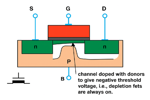
Figure 5. Depletion MOSFET Transistor
• Depletion-mode MOSFETs conduct at zero voltage and turn off with reverse bias.
3. Dual-Gate MOSFET: Provides improved isolation and control, widely used in RF amplifiers and communication circuits.
4. MESFET: Uses materials like gallium arsenide (GaAs) for high-speed microwave and satellite systems.
5. HEMT/pHEMT: Designed for ultra-high-frequency and low-noise applications such as radar and wireless communication.
6. FinFET: A 3D structure that reduces current leakage, used in modern processors and mobile devices.
7. VMOS/Power FETs: Feature a vertical current path for high efficiency in power supplies, converters, and motor control circuits.
Field-Effect Transistor (FET) Specifications
|
Specification Category |
Parameter |
Description |
|
Maximum Ratings |
VDS (Drain-Source Voltage) |
Maximum voltage between drain and source before breakdown. |
|
VGS (Gate-Source Voltage) |
Safe gate voltage range; exceeding it can damage the gate oxide. |
|
|
ID (Maximum Drain Current) |
Highest continuous current the FET can handle safely. |
|
|
PD (Power Dissipation) |
Maximum heat the device can release during operation without damage. |
|
|
DC Characteristics |
VGS(th) (Threshold Voltage) |
Determines when conduction starts. |
|
RDS(on) (On-Resistance) |
Affects efficiency and voltage drop when the device is on. |
|
|
gm (Transconductance) |
Measures how effectively gate voltage controls drain current (amplification capability). |
|
|
Dynamic Characteristics |
Capacitances (Ciss, Coss, Crss) |
Define charging and switching behavior; affect high-speed performance. |
|
Gate Charge (Qg) |
Total charge required to switch the FET; lower values improve switching speed. |
|
|
Switching Times |
Indicate how quickly the device turns on and off. |
|
|
Thermal Ratings |
Thermal Resistance |
Measures how efficiently heat moves from the junction to the case or ambient. |
|
Junction Temperature (Tj max) |
Maximum safe operating temperature for reliable performance. |
Field-Effect Transistor (FET) Circuit Designs

Figure 6. FET Circuit Design (JFET common-gate amplifier)
Field-Effect Transistor (FET) circuit designs are useful in modern electronics for amplification and switching. The circuit shown above is a JFET common-source amplifier, where voltage-rather than current-controls the transistor’s operation. The input signal passes through capacitor C1, which blocks DC and allows AC to reach the gate. Because the gate draws almost no current, the circuit offers very high input impedance, reducing signal loss. The source resistor 𝑅𝑆 provides self-biasing to stabilize the transistor’s operation, while the drain resistor 𝑅𝐷 converts current changes into amplified voltage signals. The output, taken through capacitor 𝐶2, delivers a clean amplified AC signal to the next stage. Overall, this design provides excellent voltage gain, low noise, and stable operation-qualities that make FET circuits ideal for amplifiers, buffers, and oscillators in both analog and digital systems.
Field-Effect Transistors (FET) Applications
Amplifiers and Signal Processing: FETs provide low noise and high input impedance, ideal for audio amplifiers, oscilloscopes, and sensor interfaces.
RF and Communication Systems: Used in mixers, oscillators, and amplifiers for radios, TVs, and satellite receivers due to their fast switching and low distortion.
Measurement Equipment: Common in voltmeters, electrometers, and test instruments where precision and minimal loading are important.
Integrated Circuits: The foundation of CMOS technology, powering everything from smartphones to supercomputers.
Power Electronics: Power MOSFETs are major in DC-DC converters, motor drivers, and battery systems for their fast switching and efficiency.
Signal Mixing and Modulation: Used in communication receivers for combining and processing signals with minimal distortion.
Field-Effect Transistors (FETs) vs. Bipolar Junction Transistors (BJTs)
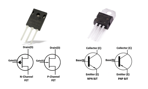
Figure 7. Field-Effect Transistors (FETs) vs. Bipolar Junction Transistors (BJTs)
|
Feature |
Field-Effect
Transistor (FET) |
Bipolar
Junction Transistor (BJT) |
|
Control Type |
Voltage-controlled device |
Current-controlled device |
|
Main Terminals |
Source, Gate, Drain |
Emitter, Base, Collector |
|
Input Impedance |
Very high (megaohms or more) |
Low to medium |
|
Power Consumption |
Low, due to minimal gate current |
Higher, requires base current |
|
Switching Speed |
Fast, ideal for digital and
high-speed circuits |
Moderate, slower due to charge
storage |
|
Gain (Amplification) |
Moderate voltage gain |
High current gain and better
linearity |
|
Thermal Stability |
Excellent; self-regulating with
temperature |
Poor; prone to thermal runaway |
|
Noise Performance |
Low noise, suitable for sensitive
circuits |
Higher noise level |
|
Operation Mode |
Voltage-controlled field effect |
Current-driven carrier injection |
|
Preferred Applications |
Digital electronics, CMOS ICs,
power switching, RF systems |
Analog amplifiers, audio
circuits, linear regulators |
|
Material Types |
MOSFET, JFET, MESFET, FinFET |
NPN, PNP (bipolar junction types) |
|
Efficiency |
High; ideal for low-power systems |
Moderate; less efficient in
switching use |
Advantages and Disadvantages of Field-Effect Transistor (FETs)
|
Advantages |
Disadvantages |
|
High input impedance allows
accurate amplification of weak signals. |
Some FETs have limited voltage
handling capability. |
|
Low power consumption makes them
ideal for portable and battery-powered devices. |
MOSFETs are sensitive to
electrostatic discharge (ESD). |
|
Low noise generation improves
signal quality in audio and RF circuits. |
FETs generally have lower gain
than BJTs. |
|
Fast switching speed supports
digital and power applications. |
Higher on-resistance can reduce
efficiency in high-current circuits. |
|
Stable thermal performance
prevents overheating and improves reliability. |
Complex manufacturing increases
production cost. |
|
Can handle high voltages (in
power MOSFETs). |
Internal capacitance and leakage
currents can affect high-frequency stability. |
Future Trends and Innovations in FET Technology
Nanometer and FinFET Designs: Modern processors now use FinFETs with 3D channels for reduced leakage and better control at nanoscale dimensions.
SiC and GaN Power FETs: Silicon carbide (SiC) and gallium nitride (GaN) devices are transforming power electronics, offering higher voltage capability, faster switching, and improved efficiency.
Flexible and Organic FETs: Developing FETs on flexible substrates for wearable tech, medical sensors, and bendable displays.
Quantum and 2D Material FETs: Materials like graphene and molybdenum disulfide (MoS₂) show potential for next-generation transistors with ultra-low power and extreme speed.
Integration in AI and IoT Devices: With the rise of edge computing and AI, low-power FETs are major to efficient data processing and smart system design.
Conclusion
The Field-Effect Transistor remains the core of modern electronics. Its voltage-controlled operation makes it efficient, reliable, and versatile for everything from processors to power systems. As technology advances with FinFETs, GaN, and SiC designs, FETs will continue to drive faster, smaller, and smarter devices in the future.
function test. The highest cost-effective products and the best service is our eternal commitment.
Hot Article
- LM358 Dual Operational Amplifier Comprehensive Guide: Pinouts, Circuit Diagrams, Equivalents, Useful Examples
- Are CR2032 and CR2016 Interchangeable?
- Understanding the Differences ESP32 and ESP32-S3 Technical and Performance Analysis
- Choosing the Right Battery: A Guide to AG4, LR626, LR66, 177/376/377, SR626, and SR626SW Equivalents
- BC547 Transistor Basics: Pinout, Application Circuits, Alternative/Complementary Models
- NPN vs. PNP: What's the Difference?
- esp32 vs stm32: which microcontroller is better for you?
- What Is a MOSFET and How It Works?
- Electrical Relay Basic: Working Operation, Types and Uses
- PNP Transistors: Structure, Working Principle and Application
 Everything You Need to Know About RMS and Peak Power in Audio Performance
2025-10-09
 Current Limiting Circuit: Features, How It Works, Uses, and Advantages Guide
2025-10-08
Frequently Asked Questions [FAQ]
1. How does temperature affect FET performance?
FETs have better thermal stability than BJTs. As temperature rises, their resistance increases slightly, which helps prevent excessive current and thermal runaway.
2. What is the role of the gate in a FET?
The gate controls the electric field that regulates current flow through the channel. By adjusting gate voltage, the FET can switch on or off or vary the current level in the circuit.
3. Can FETs be used in high-frequency applications?
Yes. Certain types like MESFETs, HEMTs, and GaN-based FETs are specifically designed for high-frequency and microwave applications, including radar, satellite, and wireless systems.
4. What are power MOSFETs used for?
Power MOSFETs are used in power conversion, motor control, and battery management systems. They can handle high current and voltage efficiently while maintaining fast switching speeds.
5. What is the difference between enhancement-mode and depletion-mode FETs?
Enhancement-mode FETs are normally off and conduct when voltage is applied to the gate. Depletion-mode FETs are normally on and require reverse gate voltage to reduce current flow.
6. How are FETs used in amplifiers?
FETs amplify weak signals with minimal distortion due to their high input impedance and low noise. They’re used in audio systems, sensors, and RF amplifiers where signal clarity is important.
Hot Part Number
 C1608X7R1E474K080AB
 C2012X5R0J225K085AA
 GRM0225C1E4R1CDAEL
 CC0603ZRY5V6BB474
 UMK316B7474ML-T
 08051U150GAT2A
 GRM1886S1H1R1CZ01D
 T495D476K010ATE080
 TPSE106M050R0500
 APA600-PQ208
- MT47H64M8CF-25E:G
- MC9S12XA512VAL
- IS42S16160B-6TL
- SI8233AD-D-IS
- RT0402DRD072K49L
- CY8C20140-SX2I
- VLF4012AT-100MR79
- SKM150GAL128D
- MC100ELT21DR2G
- MC14040BDTR2G
- LT3971AIMSE#PBF
- T491D107K006ZT7280
- UCC3818N
- INA240A2PW
- IXFP22N65X2M
- LT1999CMS8-50F#PBF
- SN74LVC32ADR
- AD5262BRUZ20-RL7
- ATMXT1666T2-C2U
- BU20360-48L
- ICS950218AFT
- MAX1779EUE+TG104
- MAX202ECWE-T
- MAX8860EUA27
- G5LA-1A4-12V
- HN29V256AOBBP-30
- M66445M1FA
- NFP-2200-A3
- PCD8010H/E31/4
- PEAD22653AFV1QH14NAR
- 6MBP150RTM060
- S29GL032A90FAIR43
- TMR3-1211
- T6TD7XBG-0001
- CS242C001PZ-TRSV
- IBMPPCBWY-GES72914
- SDINBDG4-8G-XI1
- XFL4020-332MEC
- GMOV-14D500K