74LS04 Ultimate Guide to Hex Inverters - Pin Arrangement, Principle of Operation, How to Use, Package Size
2023-12-08
30775
Catalog
The 74LS04 is a member of the 74XXYY IC series, a collection of digital logic integrated circuits. The 74LS04 features six NOT gates, performing the inverting function—hence the IC's name, which stands for "Hex Inverting Gates Logic IC." This article will explore the pin configuration, applications, and functional characteristics of the 74LS04 hex inverter.
What is the 74LS04?
The 74LS04 is a 2-input, quad, 8-bit NOT gate IC. As part of the digital logic integrated circuit family, it is also known as a hex inverter due to its six gates. Each gate consists of an input and an output, with inversion as one of its primary functions. Additionally, the 74LS04 IC boasts a wide operating voltage range, broad operating conditions, and the capability to interface directly with CMOS, NMOS, and TTL. It is one of the best ICs in the 74LS series to be used as a transistor.
Pin Configuration of 74LS04
The 74LS04 is a 14-pin integrated circuit. Below is the pin configuration for the 74LS04:

Figure 1: 74LS04 Pinout
Pin Description:
|
Pin No. |
Description |
|
INPUT
OF INVERTING GATES |
|
|
1 |
1A-GATE
Input 1 |
|
3 |
2A-GATE
Input 2 |
|
5 |
3A-GATE
Input 3 |
|
9 |
4A-GATE
Input 4 |
|
11 |
5A-GATE
Input 5 |
|
13 |
6A-GATE
Input 6 |
|
SHARED
TERMINALS |
|
|
7 |
GND-
Ground |
|
14 |
VCC-
Power supply receives positive voltage |
|
OUTPUT
OF INVERTING GATES |
|
|
2 |
1Y-OUTPUT
of GATE 1 |
|
4 |
2Y-OUTPUT
of GATE 2 |
|
6 |
3Y-OUTPUT
of GATE 3 |
|
8 |
4Y-OUTPUT
of GATE 4 |
|
10 |
5Y-OUTPUT
of GATE 5 |
|
12 |
6Y-OUTPUT
of GATE 6 |
Circuit diagram for 74LS04

Figure 2: 74LS04 Circuit Diagram
Circuit schematic for 74LS04

Figure 3: 74LS04 Circuit Schematic
Features of the 74LS04
The 74LS04 outputs TTL logic, allowing it to be used with any other TTL device and microcontrollers. It operates at a much higher speed compared to simple transistor-based inverters and is completely lead-free. It is available in various packaging options: SOIC, SOP, and PDIP. The entire 74LS04 can be used for one inverter without affecting another.
Specifications of the 74LS04
The operating temperature range is from 0°C to 70°C. The supply voltage ranges from +4.75V to +5.25V, with TTL outputs. It is entirely lead-free. The maximum current allowed through each gate output is 8mA. The maximum supply voltage is +7V, with a maximum fall time of 15ns and a maximum rise time of 15ns.
Working Principle of the 74LS04
To facilitate our better use of the 74LS04, let's first understand its key core—the NOT gate. A NOT gate is a digital logic gate that inverses the input digital signal. Designed with transistors and resistors, the transistor acts as a switch while the resistor regulates the maximum current flow. The transistor will be connected to the power supply and the resistor. The transistor's base will serve as the input, and the emitter will act as the output. Below is the circuit diagram for a NOT gate.

Figure 4: Schematic diagram of non-gate operation
The circuit operates under two conditions. When the input "A" is at a high level, the transistor begins to conduct current. Voltage from VCC starts to drive the current from VCC to ground, through the transistor, lowering the voltage at A'. The reduction in voltage results in a LOW state. On the other hand, when a low level is applied to the transistor, it ceases to conduct. This allows the power supply to provide full voltage at the output pin.
When the input of a NOT gate is low or at a logical level of 1, its output is always high or at a logical level of 0. Conversely, when the input is high or at a logical level of 0, a logical NOT gate always has a low or logical level 1 output.
|
import |
exports |
|
0 |
1 |
|
1 |
0 |
How to Use the 74LS04?
Within the 74LS04 IC, when we pair two NOT gates together, it has no effect on the output because as the first inverter changes state, the second inverter will change it back again.
Whenever we use NOT gates in series, even without a series connection, it does not affect the output. An even number of NOT gates will cancel each other out. The only odd numbers will cause a change, even if it's 1, 3, or 5. We will demonstrate this in E. coli. First, connect the NOT gate to a logic state, then check the state it will operate in according to the truth table above.
Example of Even Number of Stages:
As we can see, the input is inverted from the 74LS04 NOT gate. Now, we will use two NOT gates in series and analyze the output.
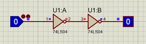
Figure 5: Working diagram of an even-numbered nongate
As you can see in the diagram, when we connect three 74LS04 NOT gates in series, applying any input has no effect on the output. Then we connect an odd number of gates to observe the result.
Example of Odd Number of Stages:

Figure 6: Working diagram of an even-numbered nongate
Stacking an odd number of NOT gates results in an effect equivalent to a single gate. Connecting them in series does not independently affect the circuit, but when we wish to change the state of a single input in any other gate, we cannot connect a non-gate at the input end. Sometimes, multiple NOT gates are also used to provide appropriate logic for a circuit.
Therefore, when multiple NOT gates are connected in series with the same wire, we must always remember when they will impact the circuit. If multiple NOT gates are connected with the same wire, we can remove them, as all gates are removed if their number is even, or just use one if it is odd, which will minimize the circuit's cost and size.
74LS04 Package

Figure 7: 74LS04 Package Diagram
The specific packaging options for the 74LS74 depend on the manufacturer and the particular model of the chip. For instance, the 74LS74 might have a suffix like 74LS74N (where 'N' typically denotes a DIP package) or 74LS74D ('D' usually indicates a SOIC package).
Applications of the 74LS04
Networking systems
Servers
Logic circuits
Memory modules for data storage
Digital magnetoresistive instruments and circuits
Equivalent Products to the 74LS04
In most cases, the CD7404 and 74LS14 can be used as substitutes for the 74LS04, but it's important to consider level shifting and power supply voltage matching issues.
74LS04 Datasheet
Click here to download IC 74LS04 PDF Datasheet: 74LS04 (Texas Instruments)
Conclusion
The 74LS04 is the best of the 74LS family for transistor-like applications. The built-in stay internal inverters each run on a single power supply, providing individual availability similar to their counterparts. The 74LS04 is also available in a variety of package forms, enhancing its adaptability to a wide range of devices. The compact and cost-effective TTL/CMOS-based IC ensures reliable compatibility with other TTL microcontroller devices - a harmonious combination of efficiency and functionality.
This is the whole content of this article, I hope it can help your life and work, if you have questions, welcome to visit ARIAT TECH, Clik here for more information.
function test. The highest cost-effective products and the best service is our eternal commitment.
Hot Article
- LM358 Dual Operational Amplifier Comprehensive Guide: Pinouts, Circuit Diagrams, Equivalents, Useful Examples
- Are CR2032 and CR2016 Interchangeable?
- Understanding the Differences ESP32 and ESP32-S3 Technical and Performance Analysis
- BC547 Transistor Basics: Pinout, Application Circuits, Alternative/Complementary Models
- Choosing the Right Battery: A Guide to AG4, LR626, LR66, 177/376/377, SR626, and SR626SW Equivalents
- NPN vs. PNP: What's the Difference?
- esp32 vs stm32: which microcontroller is better for you?
- What Is a MOSFET and How It Works?
- Electrical Relay Basic: Working Operation, Types and Uses
- PNP Transistors: Structure, Working Principle and Application
 What's ROM (Read-Only Memory)?
2023-12-11
 Guide to Ferrule Description and Uses
2025-04-29
Hot Part Number
 XA2C256-8VQG100Q
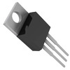 LT323AT#PBF
 CGA8P1C0G3F331K250KA
 V110B24T150BG
 MC1489ADR2
 SMAJ7.0A
 STA8090FG
 ICS664G-01
 ADG5208FBRUZ
 AD817AR-REEL
- 12065A332KAT2A
- LC87F7932BVU-SQFP-H
- AD5410AREZ
- C3225JB2A155K200AB
- UPD70F3015BGC-8EU-A
- NC7SZ157P6X
- BSC050N03LSGATMA1
- ADG438FBRZ
- V300B48H250BN
- CGA5L3X7S2A155M160AB
- TLC27L4CN
- ST62T25CB6
- MAX14983EETJ+
- RT0805BRD073K6L
- MM74C912N
- RS1D
- OPA548FKTWT
- 06035A130CAT2A
- KD224503
- AD558-6482
- AD7240JP
- BD82C602SLJKG
- CAT5221JI-10
- IDT7014S12JG8
- KFM1216Q2B-VEB8
- LM2711MTADJX/NOPB
- ML6652EH
- PW106-10
- SCC2692AC1A44G
- STC12C5406AD-35I-SOP20
- THGBM4G6D2HBAIR
- ES8680CSC
- RCAMP0514M.TBT
- S1L1491X01-T0
- LCU032420
- LM2575GR-ADJ
- 6ES7516-3FN02-0AB0
- TEN30-4813WI
- MT42L128M64D2LL-25