Frequently Asked Questions
What are the key design considerations when integrating the M83723/72W10206 into a military aviation harness assembly?
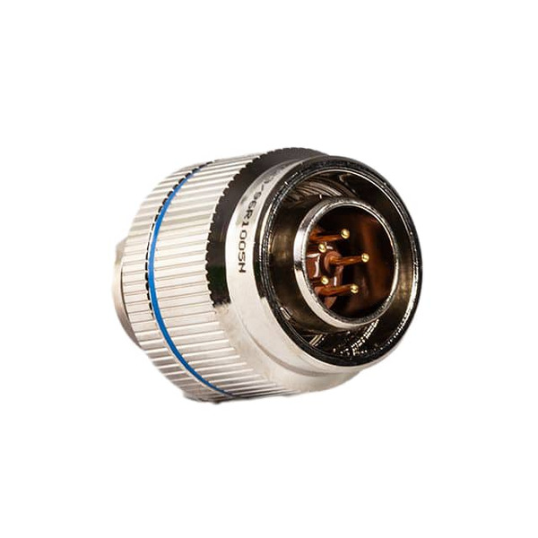
The M83723/72W10206 is a MIL-DTL-83723 Series III 2-position circular connector designed for harsh environments with an operating temperature range of -55°C to 200°C, making it suitable for aerospace thermal cycling. The bayonet lock fastening and olive drab cadmium-plated aluminum shell provide rapid panel-mount installation and environmental corrosion resistance. The 13A current rating per contact supports moderate to high-current signal or power distribution in avionics bus architectures. The gold-plated mating contacts (50.0µin thickness) ensure low contact resistance over thousands of mating cycles, critical for reliability-sensitive applications where connector wear is a lifecycle concern. When designing harnesses around the M83723/72W10206, ensure adequate strain relief at the crimp termination to prevent flexure-induced wire fracture during vibration exposure typical in aircraft engine compartments.
How does the crimp termination of the M83723/72W10206 compare to solder or wire-wrap alternatives in terms of field reworkability and process control?
Crimp termination on the M83723/72W10206 offers superior field reworkability compared to solder-terminated connectors because the contact can be removed and replaced without thermal stress to adjacent components or insulation. This advantage is particularly valuable in military and aerospace repair depots where repair documentation mandates non-destructive rework methods. The crimping process, when executed with properly calibrated tooling and wire gauge certification, produces highly repeatable contact resistance and pull-strength performance that solder joints struggle to match consistently. The M83723/72W10206 crimp contacts require tool-specific dies matched to the wire gauge (typically 12–20 AWG for 2-position configurations), so rework technicians must maintain inventory of correct tooling. Unlike wire-wrap, which can loosen under vibration, the M83723/72W10206 crimp creates a permanent mechanical lock, eliminating creep-related failures in dynamic environments.
What environmental protection does the M83723/72W10206 provide, and where are its environmental limitations?
The M83723/72W10206 is rated as environment-resistant with an olive drab cadmium-plated aluminum shell and bayonet lock, providing excellent protection against moisture ingress, salt-spray corrosion, and mechanical shock typical in military and automotive under-hood applications. The -55°C to 200°C operating range enables use in thermal extremes from arctic field operations to high-temperature engine compartments. However, the M83723/72W10206 does not include integral shielding, making it unsuitable for RF-sensitive signal routing where external EMI rejection is required; shielding must be provided by the cable assembly or harness design. The silicon rubber insert material resists hydrolysis and fungal growth better than phenolic or polyamide alternatives, supporting long-term storage in high-humidity environments. In corrosive industrial applications requiring immersion in salt water or chemical spray, the M83723/72W10206 bayonet lock mechanism should be protected with a dust cap or conformal coating on the mating surface, as the cadmium plating is sacrificial but not indefinite.
How does the 13A current rating of the M83723/72W10206 affect power distribution design in a two-wire military vehicle electrical system?
The 13A per-contact rating of the M83723/72W10206 means each of the two positions can safely carry 13A continuous current, enabling 26A total system capacity if both contacts are utilized for power distribution. In military ground vehicle wiring, this supports mid-range loads such as actuator solenoids, lighting arrays, or sensor power buses. Contact resistance heating becomes a design constraint: at 13A, a contact resistance of 5–10 mΩ (typical for gold-plated crimp contacts) dissipates 0.85–1.7W per contact. In confined mounting locations, thermal management must ensure the M83723/72W10206 shell temperature remains within the aluminum's fatigue limits under cyclic load variation. The current rating assumes proper wire gauge selection and crimping technique; undersized wire or poor crimp quality dramatically increases contact resistance and local heating, potentially causing mission-critical intermittent failures. For power applications exceeding 26A total capacity, multiple M83723/72W10206 units must be wired in parallel with balanced current distribution.
Can the M83723/72W10206 be used as a direct replacement in existing MIL-DTL-83723 Series II installations?
The M83723/72W10206 is a Series III connector and maintains physical compatibility (bayonet lock, panel-mount flange, 10-20 shell size) with Series II predecessors, but functional substitution requires validation of contact design, plating specifications, and insert material. Series II connectors often used different contact geometries, lower mating-contact plating thicknesses (typically 20–30µin), or phenolic inserts with lower temperature stability. The M83723/72W10206 50.0µm gold plating and silicon rubber insert provide improved thermal cycling durability and moisture resistance, making it a favorable upgrade for modernization programs. However, legacy harnesses designed for Series II tolerance stacks may experience intermittent mating force issues if the M83723/72W10206 is inserted into worn Series II receptacles with relaxed contact spring retention. Retrofit applications should include mechanical compatibility testing and electrical continuity validation under thermal cycling (-55°C to 200°C) to confirm performance parity before full deployment.
What is the practical mating cycle life expectancy of the M83723/72W10206, and how does it relate to maintenance planning in field operations?
Military-grade circular connectors of the M83723/72W10206 type are typically rated for 500–1000 mating cycles at the contact level, meaning connection and disconnection events. The gold-plated mating surface and steel contact springs provide this durability without significant wear or contact resistance degradation within specification limits. In aviation applications where harnesses are disconnected during scheduled maintenance (engine removal, avionics swap), the M83723/72W10206 supports a 10–15 year service life before contact wear becomes measurable. Each mating cycle contributes incremental fretting and wear; after 800+ cycles, contact resistance may approach upper tolerance limits (20–30 mΩ), warranting contact replacement during preventive maintenance. The bayonet lock mechanism itself shows minimal wear, as the locking cam surfaces are hardened steel. Field maintenance manuals for platforms using the M83723/72W10206 typically schedule contact inspection at defined cycle intervals (e.g., every 200 operational flight hours or annually, whichever occurs first) to detect early signs of pitting or corrosion.
Does the M83723/72W10206 RoHS non-compliance status restrict its use in new military or commercial aerospace platform programs?
The M83723/72W10206 is identified as RoHS non-compliant due to its cadmium plating and potential trace lead content in solder materials used in the manufacturing process. Military and aerospace programs operating under MIL-DTL-83723 specifications typically maintain exemptions from RoHS directives because the connector's environmental and reliability requirements—particularly the cadmium plating's superior corrosion resistance in harsh climates—outweigh RoHS material restrictions. Commercial aerospace platforms developed under civil certification (FAA, EASA) may encounter RoHS restrictions in supplier contracts; however, connector manufacturers have obtained formal exemptions for the M83723/72W10206 in high-reliability applications where alternatives do not meet performance thresholds. For programs with strict RoHS compliance mandates (e.g., automotive OEM platforms sold in EU markets), the M83723/72W10206 typically cannot be specified; alternative RoHS-compliant circular connectors (often with nickel-plated or tin-plated finishes) must be evaluated. Programs should clarify regulatory exemption status during design-in phase to avoid late-stage redesign risk.
What connector orientation configurations are available for the M83723/72W10206, and how does orientation selection affect harness routing and EMI management?
The M83723/72W10206 is available with orientation code 6, indicating the position of the key slot and pin arrangement relative to the mounting flange. This orientation is fixed by design; the connector cannot be reoriented in the field without mechanical modification. During harness design, orientation 6 dictates cable exit direction and keying polarity, requiring careful planning to avoid crossover routing or EMI coupling with adjacent signal lines. If a different orientation is required due to panel layout constraints, the M83723/72W10206 base part number (M83723/72) may be available in alternative orientation codes (typically 0, 2, 4, 6, 8, or 10 position series), requiring part number revision and re-qualification. The fixed orientation of the M83723/72W10206 simplifies mating polarity control—connectors cannot be inserted incorrectly—but reduces design flexibility on retrofit or adaptive platforms. Harness designers must confirm orientation 6 compatibility with existing panel cutout patterns and strain relief routing before locking component selections.
How should the M83723/72W10206 be stored and handled to maintain contact plating integrity during the supply chain and pre-installation phase?
The M83723/72W10206 gold-plated contacts can experience corrosion or tarnishing if exposed to sulfurous atmospheres, high humidity without protective storage, or rough handling that damages the plating. Military specifications require the M83723/72W10206 to be supplied with protective dust caps installed and stored in low-humidity environments (typically <40% RH) in sealed packaging with desiccant. Upon receipt, the M83723/72W10206 should be visually inspected for plating defects or oxidation; any connector showing discoloration or white corrosion products on the mating contact area should be rejected and returned to the supplier. Shelf life for the M83723/72W10206 is typically 2–3 years under proper storage; connectors stored longer should undergo contact resistance verification or be reworked with contact cleaning protocols before installation. Field technicians should not remove dust caps from the M83723/72W10206 until immediately before mating to minimize oxidation exposure. In salt-spray or high-humidity deployment environments, spare M83723/72W10206 units should be stored with silica gel packets and protective cases to prevent premature degradation.
What are the practical limitations of the M83723/72W10206 for low-level signal applications, and when is shielded connector selection necessary?
The M83723/72W10206 lacks integral shielding and is primarily designed for power distribution and moderate-bandwidth signal applications (up to kilohertz frequencies). In analog or RF signal chains where noise floor is a limiting factor—such as sensor signal conditioning, telemetry receivers, or precision measurement systems—the M83723/72W10206 unshielded configuration allows capacitive and inductive coupling from adjacent harnesses and high-current power cables. If the M83723/72W10206 must carry low-level signals (millivolt-range analog or RF bands), external shielding via braided cable or foil wrap must be incorporated, with shield termination at the connector backshell or integrated shield contact (not available in the 2-position M83723/72W10206). For military avionics applications transmitting or receiving RF signals (1–40 GHz), the M83723/72W10206 is unsuitable without additional filtering and isolation; shielded circular connectors (MIL-DTL-38999 or MIL-DTL-83723 variants with integral shield contacts) are specified instead. In noise-sensitive automotive applications such as engine control modules or radar receivers, the M83723/72W10206 may introduce unacceptable EMI if routed near high-current power harnesses; parallel shielding and routing separation are required.
How does the silicon rubber insert material of the M83723/72W10206 perform compared to phenolic or polyamide alternatives under thermal cycling and humidity stress?
The M83723/72W10206 silicon rubber insert provides superior dimensional stability and moisture absorption resistance compared to phenolic or polyamide materials over extended thermal cycling (-55°C to 200°C). Phenolic inserts, common in older connector designs, exhibit micro-cracking and stress relaxation at temperature extremes, leading to mechanical looseness and increased contact resistance variance after 100+ thermal cycles. Polyamide inserts absorb moisture in humid environments, causing dimensional swelling and loss of contact retention force. The M83723/72W10206 silicon rubber insert exhibits minimal hysteresis through thermal cycling and absorbs <0.5% moisture by weight, maintaining consistent contact spring force and mating mechanics throughout platform service life. However, silicone rubber can degrade in the presence of ozone, temperature extremes >200°C, or prolonged exposure to certain organic solvents used in avionics cleaning and maintenance. For military platforms operating in high-altitude UV environments or near high-voltage equipment generating ozone, the M83723/72W10206 silicone insert may require protective sleeving or periodic visual inspection for surface degradation.
What crimping tool compatibility and contact gauge verification procedures are required to ensure field rework quality on the M83723/72W10206?
The M83723/72W10206 crimp contacts are sized for specific wire gauges (typically 12–20 AWG depending on contact variant), and tool-specific die sets must be used to achieve correct crimp geometry, contact resistance, and pull-strength performance. Military maintenance manuals for the M83723/72W10206 specify tool part numbers and calibration intervals (typically 500–1000 cycles or annually) to ensure die wear does not drift outside specification. Field technicians performing M83723/72W10206 rework must verify wire gauge matching before crimping; using undersized wire or incorrect dies produces contacts with excess resistance (>20 mΩ) and reduced pull strength, causing intermittent failures or complete loss of signal/power. Post-crimp contact resistance verification using a micro-ohmmeter (resolution ≤1 mΩ) is typically performed on 10% sample batches or 100% inspection for safety-critical circuits. Pull-strength testing on sample contacts ensures the crimp is mechanically sound; the contact should not release from the wire under 20–30 lbf axial tension. The M83723/72W10206 contact variant part number (e.g., 0211-2060-99 for 12 AWG, 0211-2061-99 for 16 AWG) must be cross-referenced with the tool catalog to prevent installation of incompatible dies.
In what ways does the bayonet lock mechanism of the M83723/72W10206 reduce mating errors and improve reliability compared to threaded or push-pull connectors?
The M83723/72W10206 bayonet lock uses a quarter-turn or half-turn rotational motion to engage two or four locking lugs on the shell, creating a positive mechanical lock that resists accidental disconnection under vibration, shock, or thermal expansion/contraction cycling. Unlike threaded connectors (which require multiple rotations and are prone to cross-threading), the M83723/72W10206 bayonet lock completes in one quick motion, reducing assembly time and operator error in field maintenance. The locking engagement creates a repeatable axial preload on the contact carrier, maintaining consistent contact force through vibration without fretting or micro-motion that causes intermittent failures in weakly-latched designs. Military and aerospace platforms operating in high-vibration environments (rotorcraft, heavy vehicles) specify bayonet-lock connectors like the M83723/72W10206 specifically to prevent in-flight or in-mission disconnection events. However, the M83723/72W10206 bayonet lock requires deliberate rotation to release; accidental operation is less likely than with push-pull connectors but requires operator training to prevent forcing or cross-threading the locking cam.
What are the thermal management considerations for the M83723/72W10206 when operating at full current load (13A per contact) in confined mounting spaces?
At 13A per contact, the M83723/72W10206 aluminum shell acts as a heatsink for I²R losses in the contacts and wiring. In well-ventilated panel-mount locations, convective cooling is typically sufficient to maintain shell temperature <50°C above ambient. In confined spaces (sealed equipment enclosures, potted assemblies), the M83723/72W10206 mounting flange should be thermally coupled to the panel or chassis to conduct heat away; thermal interface materials (silicone pads, 1–5 W/mK conductivity) may be used to improve heat transfer. The -55°C to 200°C operating range assumes the M83723/72W10206 shell does not exceed 200°C; under high ambient temperature (e.g., 85°C engine compartment) and 13A load with poor thermal coupling, contact temperature can approach or exceed specification limits within minutes. Thermal modeling or measurement during prototype testing is advised for platforms where the M83723/72W10206 operates continuously at rated current in high-ambient conditions. Adding ventilation, increasing panel thickness for heat spreading, or specifying lower-resistance contacts (specialty gold-plated variants) may be necessary to maintain safe thermal margins.
How should the M83723/72W10206 be specified and validated in design requirements documentation to ensure supplier consistency and prevent performance degradation through component revisions?
The M83723/72W10206 full part number must be specified in design documentation along with applicable revision status, material certifications, and test performance metrics. Key specification callouts for the M83723/72W10206 should include: (1) MIL-DTL-83723 Series III compliance with manufacturing process audits; (2) contact plating specification (50.0µm ±10% gold); (3) insert material (silicon rubber, per MIL-DTL-38999 or equivalent); (4) environmental qualification (salt-spray per ASTM B117, thermal cycling per MIL-STD-810G); (5) electrical acceptance criteria (contact resistance <10 mΩ, insulation resistance >1000 MΩ at 500V DC); and (6) mechanical pull-strength and vibration endurance testing. Supplier changes to the M83723/72W10206 manufacturing process, contact plating thickness, or insert material can degrade performance without changing the part number; design teams should implement supplier approval lists and periodic lot sampling to detect drift. For long-term platform sustainment, the M83723/72W10206 datasheet should be archived with supporting test reports to establish a performance baseline, enabling detection of future supplier non-conformances or obsolescence risks.